Manufacturing tool for fluid dynamic bearing

a technology of fluid dynamic bearings and manufacturing tools, which is applied in the direction of manufacturing tools, sliding contact bearings, mechanical equipment, etc., can solve the problems of imposing difficulty in high precision in the manufacture of apparatus, and achieve the effect of high precision and easy manufacturing

Inactive Publication Date: 2007-08-07
HON HAI PRECISION IND CO LTD
View PDF7 Cites 4 Cited by
  • Summary
  • Abstract
  • Description
  • Claims
  • Application Information

AI Technical Summary

Benefits of technology

[0008]The present invention is directed to a fluid dynamic bearing manufacturing tool which has a high precision and is relatively easier to be manufactured.

Problems solved by technology

These separate components impose difficulty to manufacture the apparatus with high precision, since it is required not only that the discrete components be precisely manufactured, but also that the discrete components be precisely assembled.

Method used


Image

  • Manufacturing tool for fluid dynamic bearing
  • Manufacturing tool for fluid dynamic bearing
  • Manufacturing tool for fluid dynamic bearing

Examples


Embodiment Construction

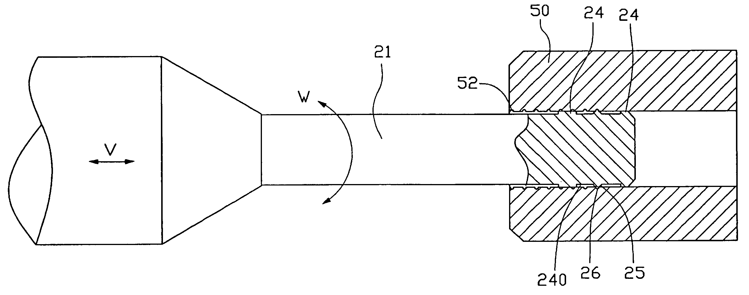
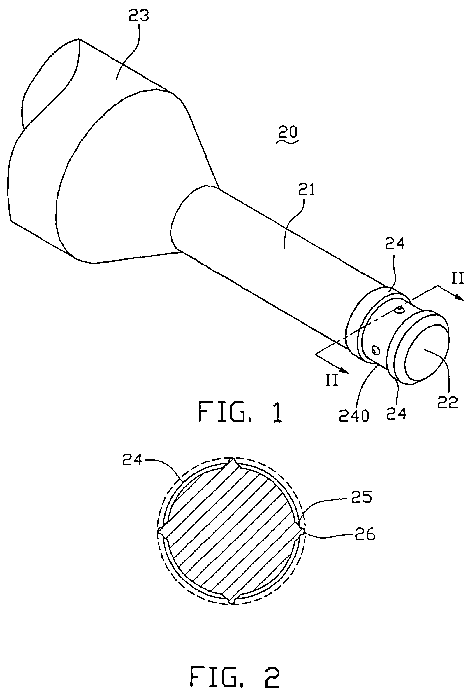
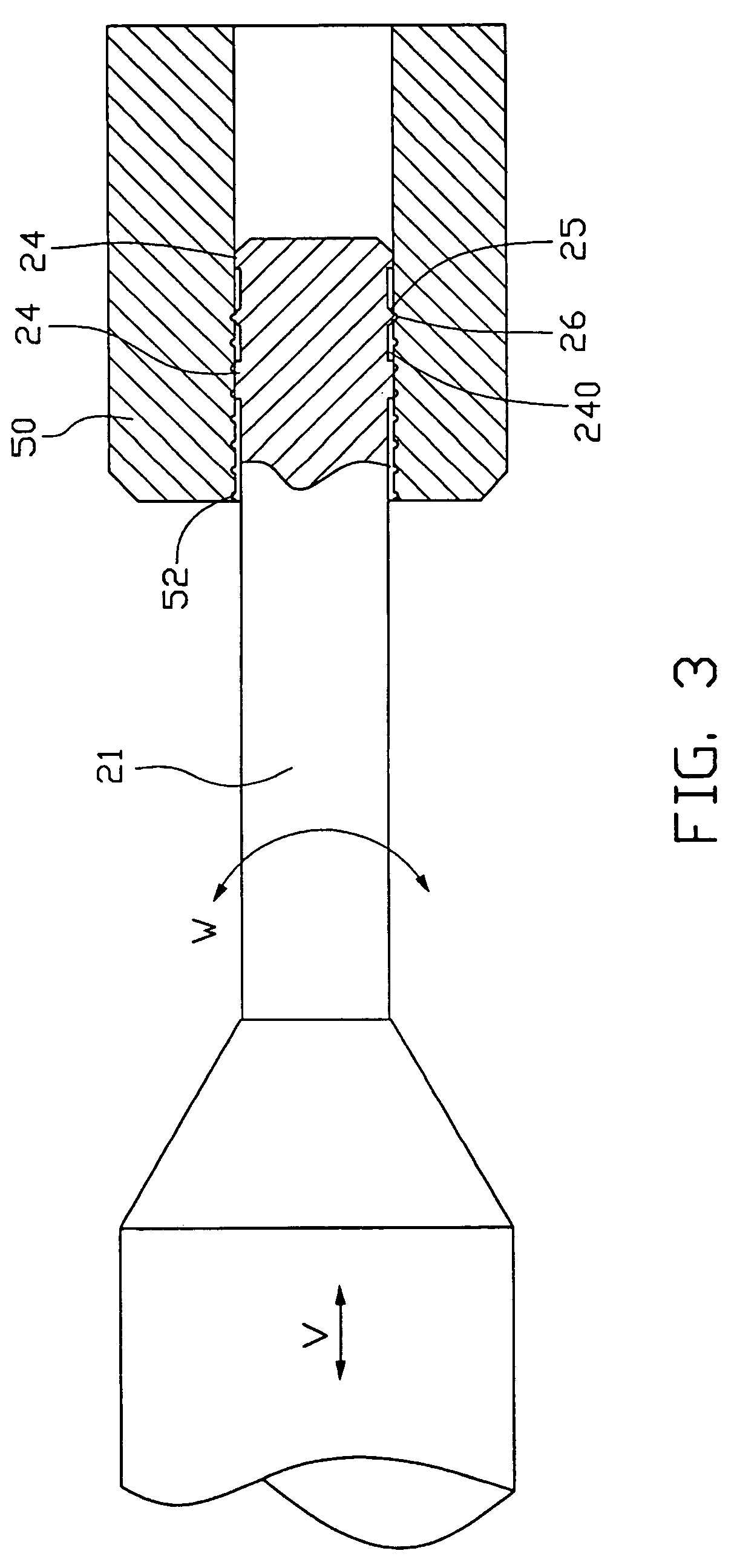
[0016]FIGS. 1 and 3 illustrate by way of example a manufacturing tool 20 in accordance with a preferred embodiment of the present invention, for forming a dynamic pressure generating groove 52 (Hereinafter referred to as “groove”) of a bearing sleeve 50.

[0017]The manufacturing tool 20 comprises a tool shaft 21 having a leading end 22 and an opposite coupling end 23. The coupling end 23 is for being connected to axial and rotational drive means to simultaneously apply a rotational speed (W) and an axial feeding speed (V) to the tool shaft 21 with respect to the bearing sleeve 50.

[0018]A pair of axially spaced guiding flanges 24 is formed around the leading end 22 of the tool shaft 21. Each guiding flange 24 is cylindrical and has an outer circumference that is concentric with the tool shaft 21. An annular recess 240 is thus formed around the tool shaft 21 between the guiding flanges 24. The outer diameter of the guide flange 24 is equal to or slightly less than the inner diameter of ...


PUM

PropertyMeasurementUnit
dynamic pressureaaaaaaaaaa
outer diameteraaaaaaaaaa
diameteraaaaaaaaaa

Abstract

A manufacturing tool (20) for forming a dynamic pressure groove (52) in an inner peripheral surface of a bearing sleeve (50) includes a tool shaft (21) for being rotated in a bore of the bearing sleeve while being moved in an axial direction thereof. Protrusions (25) are integrally and circumferentially arranged on an outer periphery of the tool shaft near a leading end (22) thereof. Machining tips (26) are integrally formed on outmost ends of the protrusions for machining the inner peripheral surface of the bearing sleeve to form the dynamic pressure groove therein.

Description

TECHNICAL FIELD[0001]The present invention relates generally to tools for manufacturing fluid dynamic bearings, and more particularly to a manufacturing tool for forming a dynamic pressure generating groove on a fluid dynamic bearing.BACKGROUND[0002]Due to request for low abrasion on rotational elements to achieve an extended life and for low extent of noise, fluid dynamic bearings (FDBs) have been used in fan motors and hard disk drive motors.[0003]As shown in FIG. 4, in an FDB, a rotary shaft 5 is rotatably inserted into a sleeve 3 with a bearing clearance formed between the rotary shaft 5 and the sleeve 3. A dynamic pressure generating groove 3A is formed on an inner peripheral surface of the sleeve 3. Lubricating oil is applied to the bearing clearance. A pressure is generated due to the pumping action of the dynamic pressure generating groove 3A caused by the rotation of the rotary shaft 5. As a result, the rotary shaft 5 rotates in the sleeve 3 without radial contact with the ...

Claims


Application Information

Patent Timeline
Patent Type & Authority Patents(United States)
IPC IPC(8): B21D1/02
CPCB21H7/187F16C17/026F16C33/1065F16C33/14Y10T29/53104Y10T409/4028Y10T407/16F16C2220/60F16C2220/68
Inventor SHIH, WUN-CHANGLIN, HUAN-CHAOHUANG, CHING-HSINGHONG, CHIEN-LONGPEI, HSIEN-SHENG
Owner HON HAI PRECISION IND CO LTD
Why Eureka
Try Eureka