Pressure sensor system with semiconductor chip and antenna member

a technology of pressure sensor and antenna member, which is applied in the direction of fluid pressure measurement, measurement device, instruments, etc., can solve the problem of not revealing an embodiment capable of measuring pressure with high accuracy, and achieve the effect of high accuracy and high accuracy

Active Publication Date: 2007-08-07
HITACHI LTD
View PDF4 Cites 21 Cited by
  • Summary
  • Abstract
  • Description
  • Claims
  • Application Information

AI Technical Summary

Benefits of technology

[0019]By including the above described embodiments, pressure measurement with high accuracy can be achieved. Also, the measurement with high accuracy can be performed when using the pressure sensor system in an embodiment in which the pressure sensor system is fixed to the object to be measured.

Problems solved by technology

However, the above described document does not disclose an embodiment which is capable of measuring pressure with high accuracy.
Also, the above described document does not disclose an embodiment which is capable of performing highly accurate measurement when a pressure sensor is used in a state of being fixed to an object to be measured.

Method used


Image

  • Pressure sensor system with semiconductor chip and antenna member
  • Pressure sensor system with semiconductor chip and antenna member
  • Pressure sensor system with semiconductor chip and antenna member

Examples


second embodiment

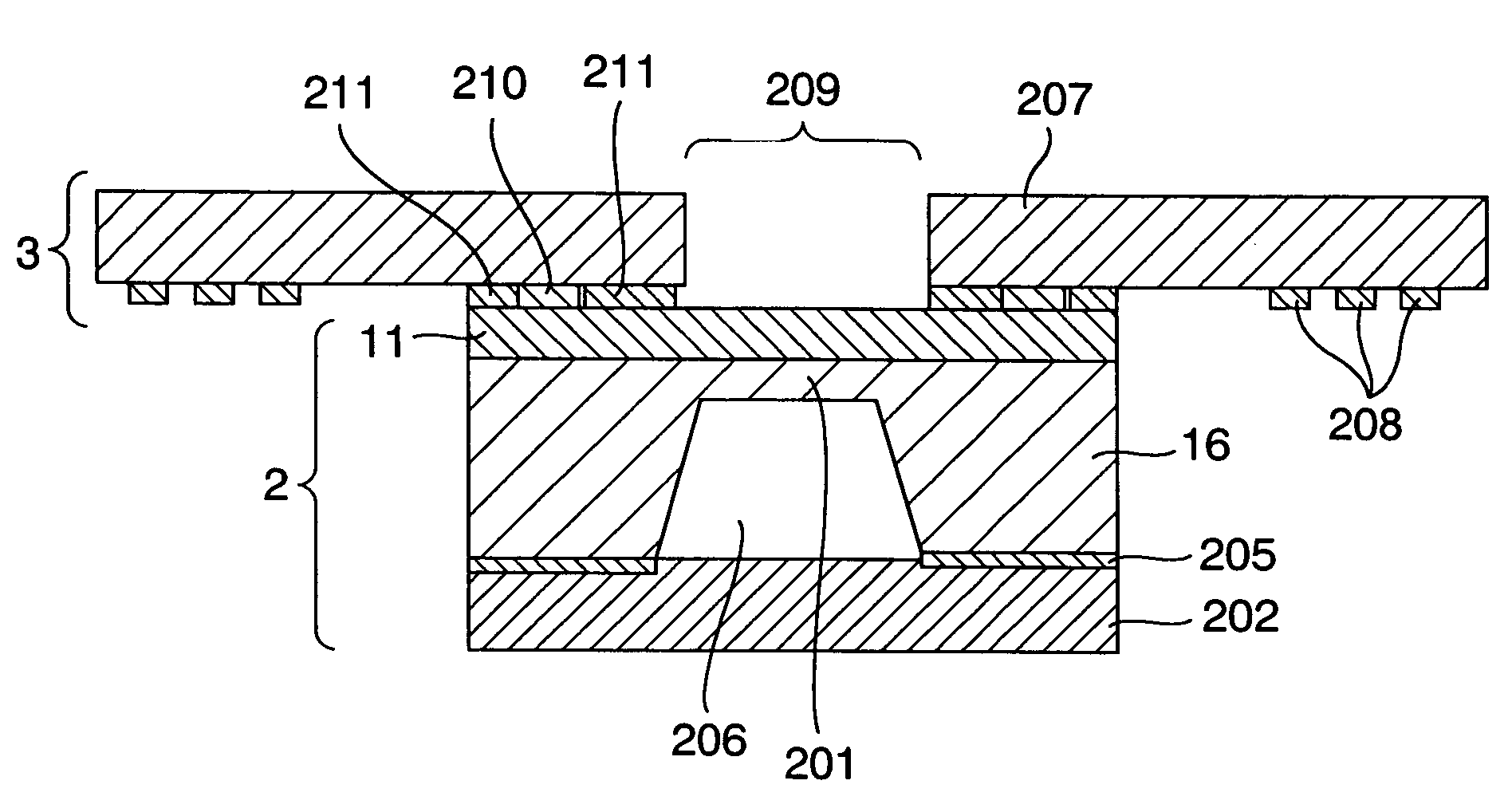
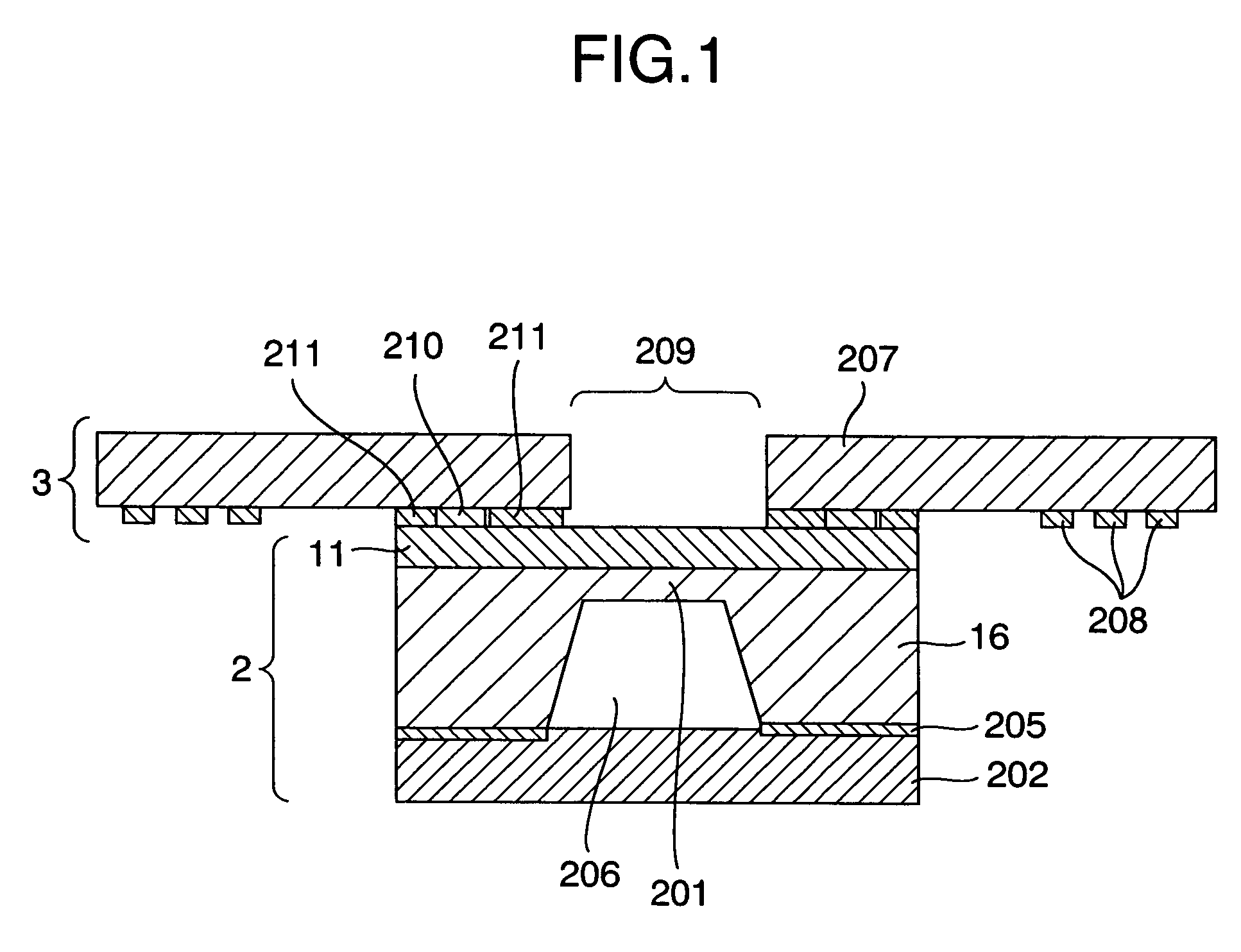
[0082]the present invention is the case where a back surface of the sealing part 202 is brought into contact with the film 207 as shown in FIG. 18. A surface on an opposite side to an element forming surface of the silicon chip is placed on the film 207. The connecting part 210 and the antenna 208 are electrically connected with a metal material 213 such as wire bonding and a metal thin plate. In this case, the diaphragm 201 and the film 207 do not interfere with each other, and therefore, accurate pressure measurement becomes possible. Since rigidity of the film 207 is added to the rigidity of the silicon chip 2, the strain applied to the diaphragm part 201 and the device forming surface 11 can be made small even when an external force such as bending stress is loaded, and therefore, the advantage of being capable of measuring with high accuracy is provided. This embodiment is characterized by including a film or a plate, a silicon chip capable of measuring pressure and an antenna,...

first embodiment

[0086]FIG. 22 shows a pressure measuring system using the pressure sensor system 1 of the present invention. The pressure sensor system 1 which measures absolute pressure is provided inside a container 216, and a measurement value of the pressure sensor system 1 is received by the reader 15 provided outside the container 216 by wireless, and is stored in an information storing part in the reader 15 which records information. The film 207 is fixed in the state substantially parallel with an inner wall of the container 216. The surface of the silicon chip on the opposite side to the surface where the diaphragm side is formed is located on the inner wall side of the container 216. In this manner, the inner wall of the container 216 is placed so as to be close to the sealing part 202, and the diaphragm part 201 is placed so as not to interfere with the inner wall of the container 216. As shown in FIG. 23, the surface of the silicon chip 2 where the diaphragm is formed is formed to be lo...


PUM

PropertyMeasurementUnit
areaaaaaaaaaaa
magnetic permeabilityaaaaaaaaaa
pressureaaaaaaaaaa

Abstract

In order to realize a compact wireless pressure sensor system which transmits an accurate pressure value, the present invention provides a pressure sensor system constructed at least by a silicon chip on which a circuit operated by electromagnetic wave energy is mounted, and a film which supports an antenna, in which film a through-hole is provided in the vicinity of a diaphragm part.

Description

BACKGROUND OF THE INVENTION[0001]The present invention relates to a pressure sensor system for detecting dynamical quantity such as pressure of gas or fluid.[0002]A tag referred to as an RF tag, in which electric power supplied by electromagnet induction is used to activate a circuit to transmit a previously set ID number by a radio wave, is developed and starts to be applied to physical distribution management and management of admission tickets and the like. A trial to transmit a temperature measurement value by wireless by connecting a temperature sensor to such an ID tag is also performed. For example, a sensor-equipped ID tag is constructed by connecting a temperature sensor to an RF tag circuit on a printed wiring board, and by integrally molding those with plastic in a state of being mounted on the printed wiring board, as shown in JP-A-2001-187611.BRIEF SUMMARY OF THE INVENTION[0003]However, the above described document does not disclose an embodiment which is capable of mea...

Claims


Application Information

Patent Timeline
Patent Type & Authority Patents(United States)
IPC IPC(8): G01L9/00
CPCG01L9/0055
Inventor OHTA, HIROYUKISUMIGAWA, TAKASHI
Owner HITACHI LTD
Why Eureka
Try Eureka