Light string socket with mechanical shunt

a technology of mechanical shunt and socket, which is applied in the direction of lighting support devices, coupling device connections, lighting and heating apparatus, etc. it can solve the problems of tedious task of finding which socket is missing its bulb, and the entire series will lose electric power, and achieve the effect of convenient insertion of the shunt holder

Inactive Publication Date: 2007-08-07
PAN KUO AN +1
View PDF35 Cites 69 Cited by
  • Summary
  • Abstract
  • Description
  • Claims
  • Application Information

AI Technical Summary

Benefits of technology

[0006]According to its major aspects and briefly recited, the present invention is a lamp having a mechanical shunt, which lamp is useful in strings of lights where the lights are arranged in an electrical series. The present lamp includes a transparent globe with a filament and two external Dumet wires, a base to which the globe is attached and through which the Dumet wires extend, a socket for receiving the base, two conductive electrical contacts inside the socket, parallel to its long dimension, and attached to the interior of the socket wall, a conductive shunt and a shunt holder. The shunt holder is carried by the socket along with the shunt and holds the shunt in a nearly horizontal orientation except for its lateral edges. The edges of the shunt extend to opposing sides of the shunt holder and depend at a small angle in order to engage the electrical terminals on the socket wall. In addition, the shunt holder has non-conductive bar extensions extending laterally below the shunt to facilitate insertion of the shunt holder into the socket and to further isolate the shunt electrically when the lamp base is inserted into the socket.

Problems solved by technology

When thus arranged, the removal of one lamp will cause an open circuit and the entire series will lose electric power.
In a set of Christmas lights on a Christmas tree, for example, it is a tedious task to find which socket is missing its bulb.

Method used


Image

  • Light string socket with mechanical shunt
  • Light string socket with mechanical shunt
  • Light string socket with mechanical shunt

Examples


Embodiment Construction

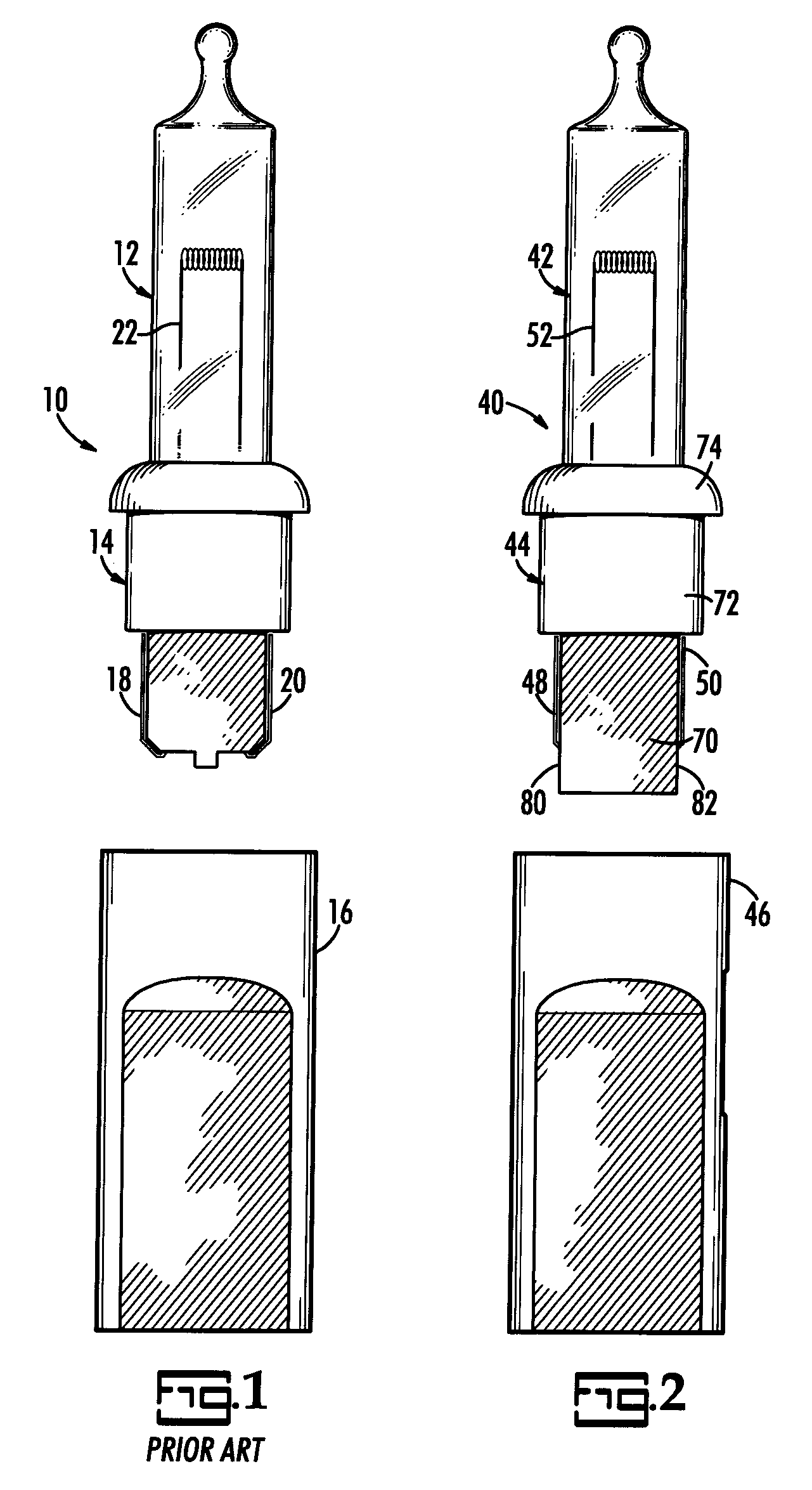
[0024]FIG. 1 illustrates a prior art lamp, generally indicated by reference number 10, as viewed from the side, and with a globe 12 in its base 14 removed from its socket 16. Dumet wires 18, 20, extend from the bottom of base 14 and are bent laterally and upwardly along the sides of base 14. Dumet wires 18, 20, pass through base 14 into globe 12 and are in electrical connection with a filament 22 in globe 12 to form an electrical circuit when a voltage is applied across Dumet wires 18, 20.

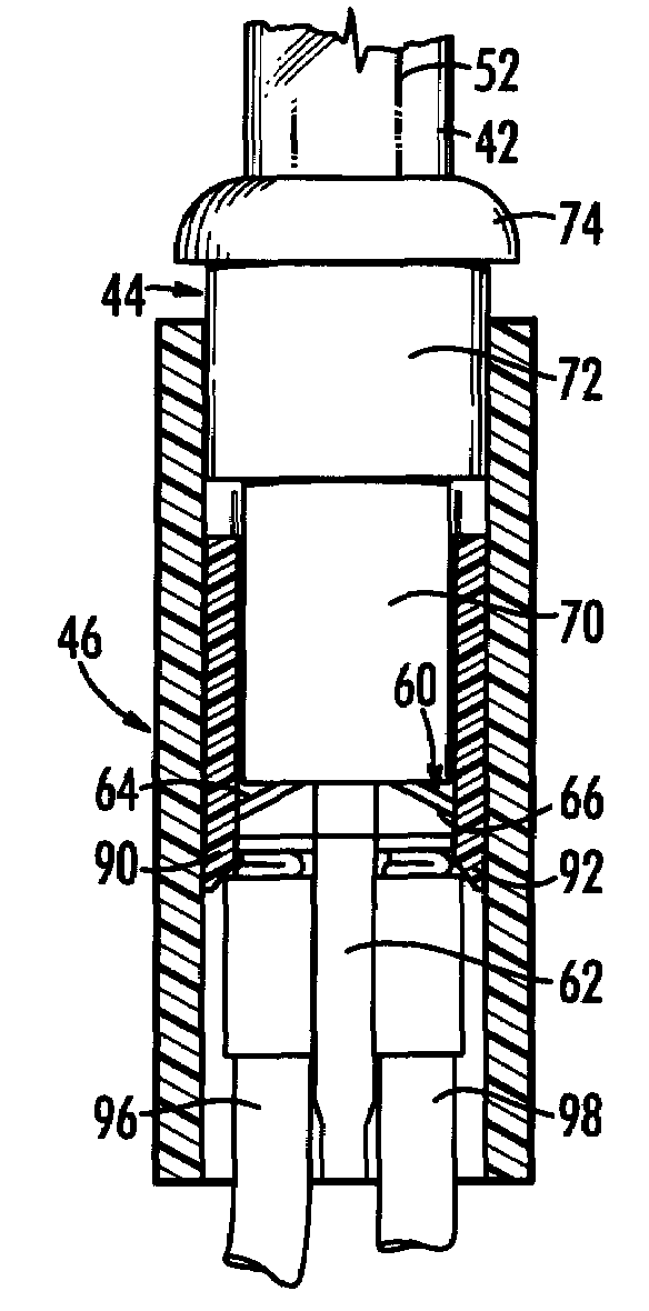
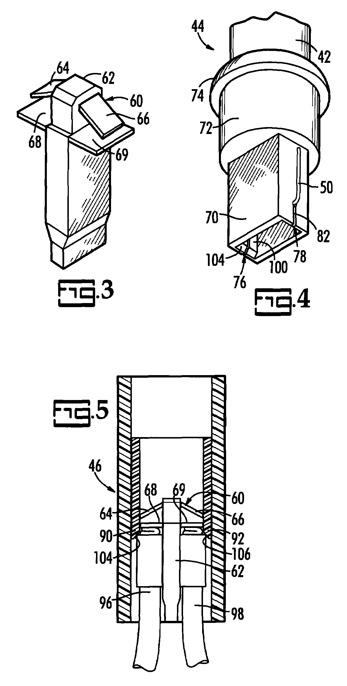
[0025]FIG. 2 allows comparison of the present inventive lamp 40 to lamp 10 of prior art FIG. 1. Lamp 40 also has a globe 42, a base 44, and a socket 46. Dumet wires 48, 50, exit base 44 from the side rather than the bottom and extend upwardly from the exit point along the sides of base 42. Dumet wires 48, 50 pass through base 44 into globe 42 and are in electrical connection with filament 52 in order to form a circuit when Dumet wires 48, 50 are connected to a source of electricity. It will be appr...


PUM


Abstract

A lamp for a light string has a mechanical shunt to allow current to pass to the next light in the event of a missing bulb. A resilient shunt is held in a generally lateral orientation by a shunt holder within the socket. When the hollow base with its bottom opening is inserted into the socket, the walls of the base cam the ends of the shunt away from the electrical contacts on the walls of the socket. Likewise, when the base is removed, the resilient lateral ends of the shunt return to engage the electrical contacts. The timing of the contact by the shunt with the electrical contacts avoids arcing. Additionally, slits formed in the wall of the base allows the Dumet wires to exit the sides of the base in the correct location for engaging the electrical contacts, thus reducing the instances of misaligned Dumet wires.

Description

CROSS REFERENCE TO RELATED PATENTS[0001]The priority benefit of U.S. provisional patent application Ser. No. 60 / 873,659, filed Dec. 8, 2006, is claimedBACKGROUND OF THE INVENTION[0002]The present invention relates to shunts for lamps, particularly lamps arranged in an electrical series with other lamps to prevent all the lamps in the series from losing power when one lamp is removed from its socket.[0003]Lamps such as those in decorative light strings are often arranged electrically in series. When thus arranged, the removal of one lamp will cause an open circuit and the entire series will lose electric power. In a set of Christmas lights on a Christmas tree, for example, it is a tedious task to find which socket is missing its bulb. Unless the empty socket is spotted by luck, one must begin at one end of the string and look at each socket in turn until all of the empty sockets are found.[0004]There have been many attempts to produce shunts to keep power flowing to subsequent lamps ...

Claims


Application Information

Patent Timeline
Patent Type & Authority Patents(United States)
IPC IPC(8): H01J5/50F21V21/00H01R33/06
CPCH01J5/56H01R33/09F21S4/001F21S4/10
Inventor GIBBONEY, JAMES W.
Owner PAN KUO AN
Why Eureka
Try Eureka