Hybrid vehicle

a hybrid vehicle technology, applied in the direction of electric propulsion mounting, cycle equipment, electric propulsion, etc., can solve the problems of difficult to achieve size reduction, achieve the effect of improving layout efficiency, suppressing power consumption, and improving layout efficiency

a hybrid vehicle technology, applied in the direction of electric propulsion mounting, cycle equipment, electric propulsion, etc., can solve the problems of difficult to achieve size reduction, achieve the effect of improving layout efficiency, suppressing power consumption, and improving layout efficiency

US7255188B2Inactive Publication Date: 2007-08-14HONDA MOTOR CO LTD

Image

  • Hybrid vehicle
  • Hybrid vehicle
  • Hybrid vehicle

Examples


Embodiment Construction

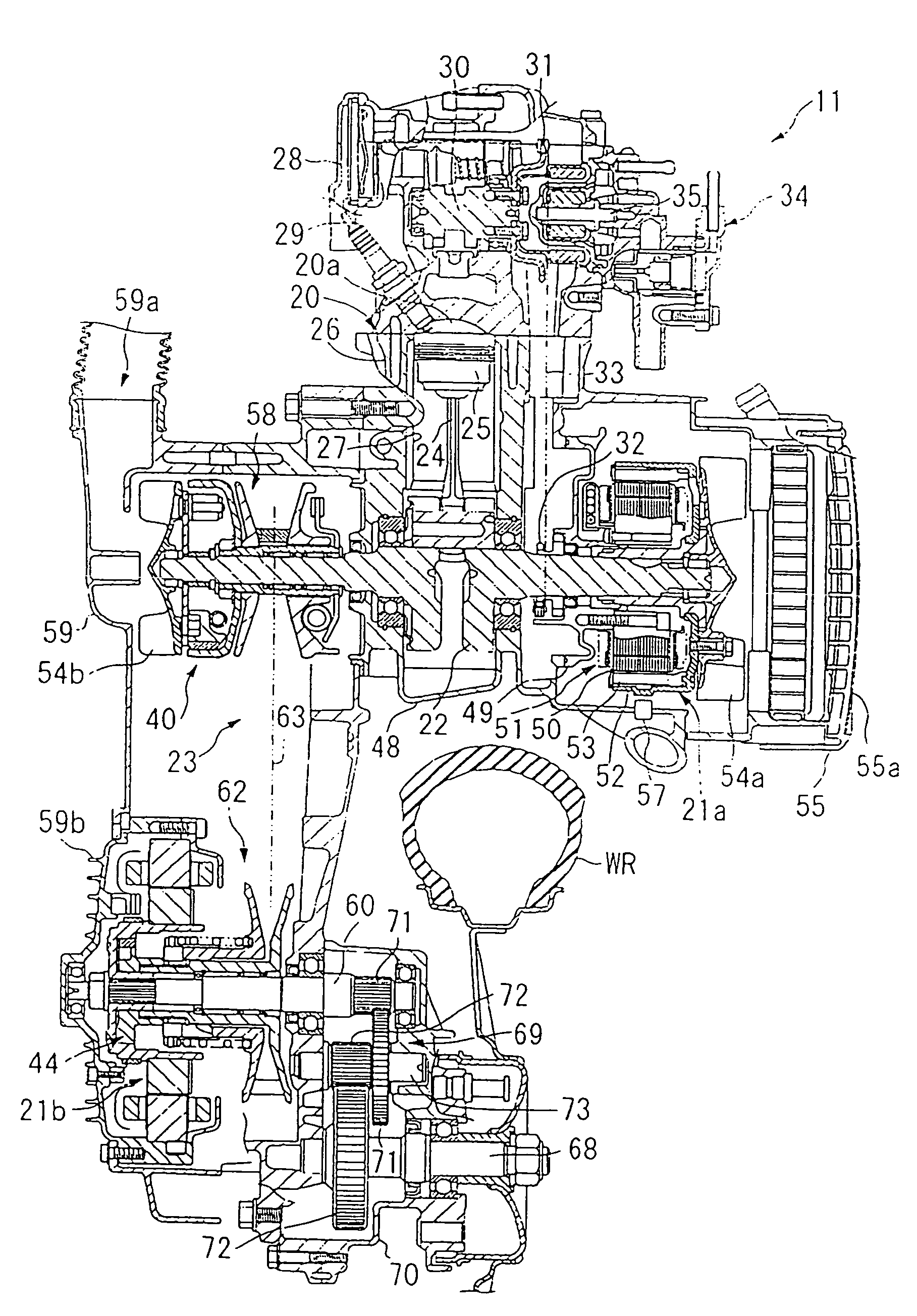
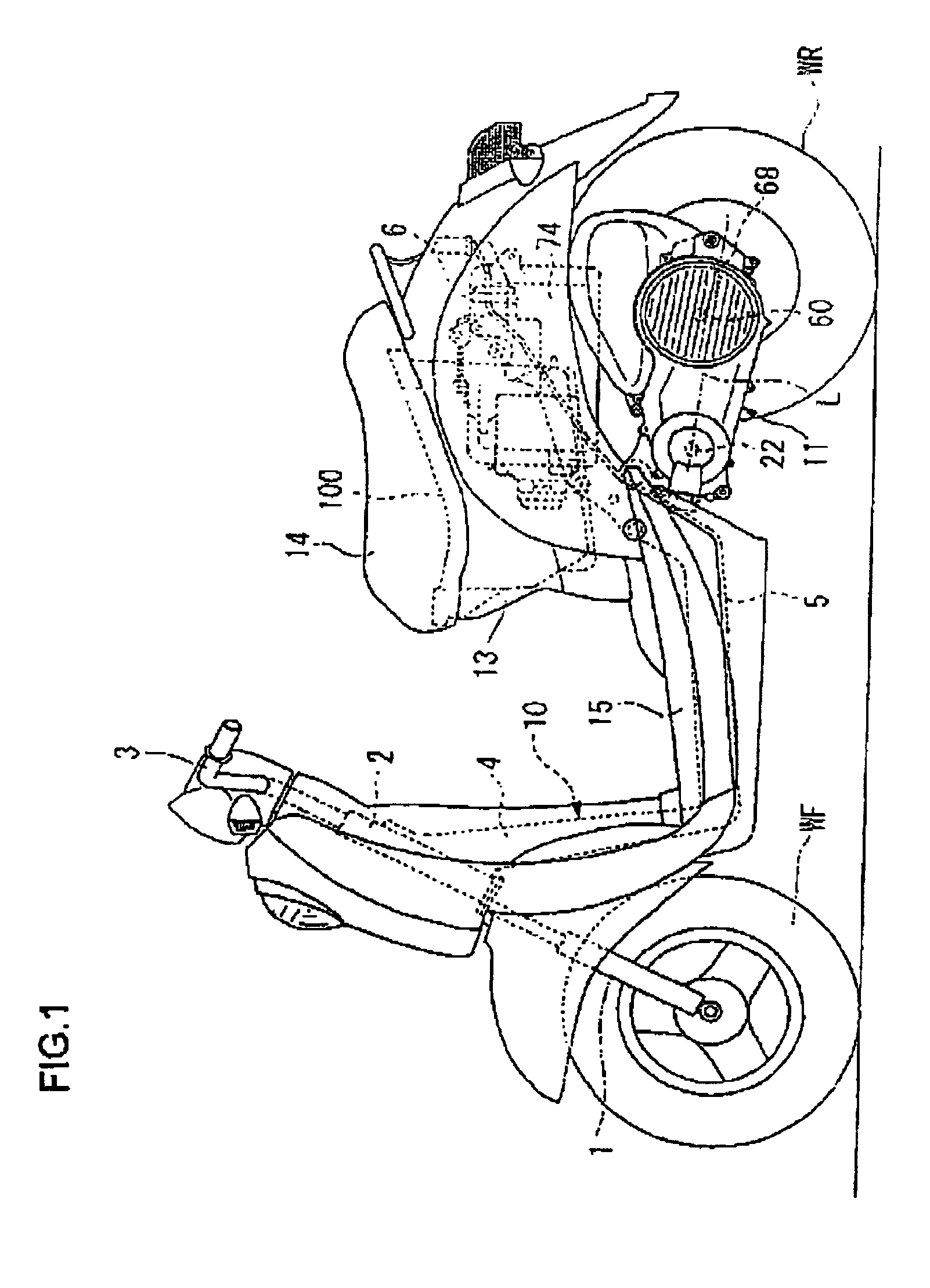
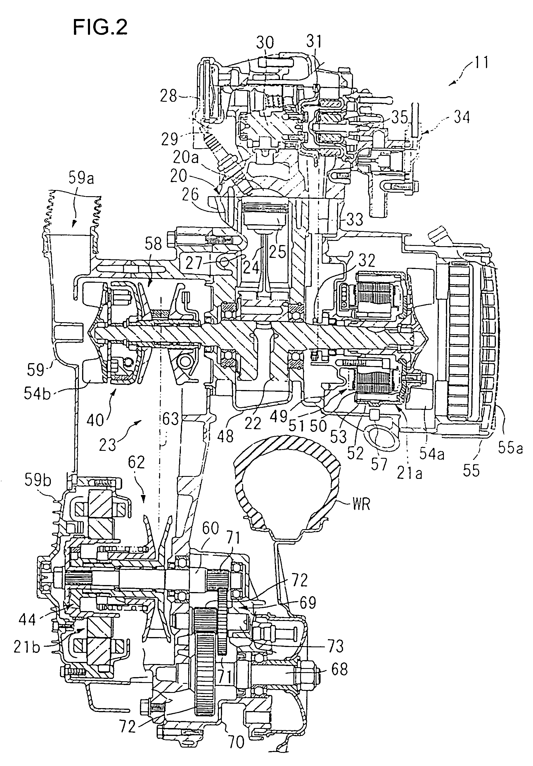
[0017]An embodiment of a hybrid vehicle of the present invention will now be described in the following with reference to the drawings of FIG. 1 to FIG. 4. In the following description, front side refers to the advancing direction of the vehicle, and right side and left side refer to the right side and the left side facing in the advancing direction of the vehicle.

[0018]As shown in FIG. 1, a hybrid vehicle of this embodiment is unit swing type two-wheeled vehicle, having a front fork 1 where a front wheel WF is axially supported at the front of the vehicle. This front fork 1 is pivoted on a head pipe 2, and can be steered by operating a handle 3. A downpipe 4 running to the rear and down is attached from the head pipe 2, and a middle frame 5 extends substantially horizontally from a lower end of this down pipe 4. Also, a rear frame 6 is formed running rearwards and upwards from a rear end of the middle frame 5. One end of a power unit 11, as a drive power source, is pivoted to the v...


PUM


Abstract

In order to do away with the need for a power source switching operation, and to improve motor regeneration charge efficiency in a hybrid vehicle, a one-way clutch is provided between an internal combustion engine and an electric drive motor.

Description

FIELD OF THE INVENTION[0001]This invention relates to a hybrid vehicle having an internal combustion engine and an electric motor as power sources.BACKGROUND OF THE INVENTION[0002]Japanese patent laid-open No. Hei. 8-175473 discloses a hybrid vehicle that can switch between travel using an electric motor only and travel using an internal combustion engine only depending on travel conditions of the vehicle for the purpose of achieving lowered fuel consumption and lowered exhaust gas pollution. The hybrid vehicle has power from an internal combustion engine transmitted to a drive wheel by means of a V-belt type power transmission unit and a centrifugal clutch, and an electric motor is also connected to this drive shaft via a switching mechanism for carrying out switching of power of the V-belt transmission unit.[0003]With the structure described above, since the centrifugal clutch is arranged between the drive shaft and the V-belt transmission unit, in the cases such as where a person...

Claims


Application Information

Patent Timeline
14 Aug 2007
Publication
US7255188B2
IPC
B60K6/04; B60K1/00; B60K6/36; B60K6/383; B60K6/40; B60K6/442; B60K6/543; B60K17/04; B60L50/16; B62J99/00; B62M7/12; B62M9/04; B62M23/02
CPC
B60K6/383; B60K6/40; B60K6/48; B60K6/543; B60L11/14; Y02T10/70; B60L2200/12; B60Y2200/12
Inventors
TSUKADA, YOSHIAKI; KUROKI, MASAHIRO