
VSWR tolerant power detector

a power detector and tolerant technology, applied in amplifiers, amplifiers with semiconductor devices/discharge tubes, electrical devices, etc., can solve the problems of increasing the probability of dropped calls in fringe areas, reducing the quality of service, and loading impedance, so as to prevent a reduction in signal amplitude

Active Publication Date: 2007-08-14
QORVO US INC
View PDF12 Cites 16 Cited by
  • Summary
  • Abstract
  • Description
  • Claims
  • Application Information

AI Technical Summary

Benefits of technology

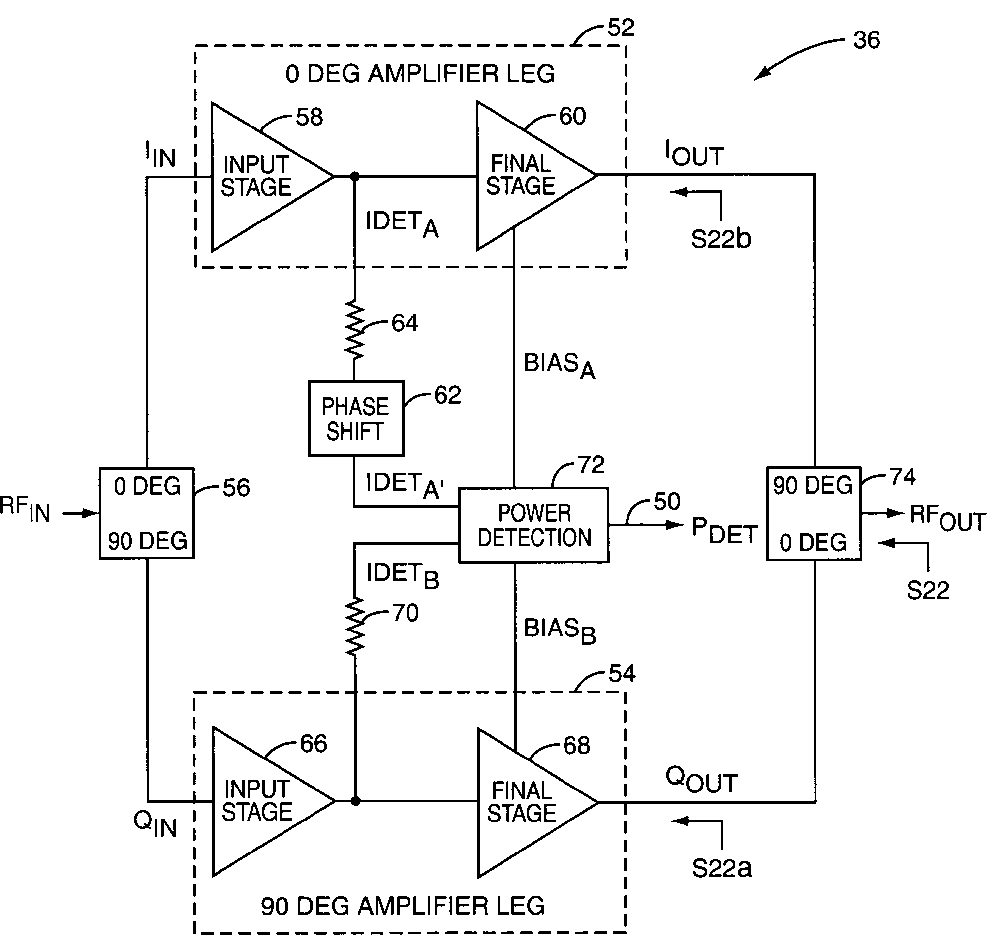
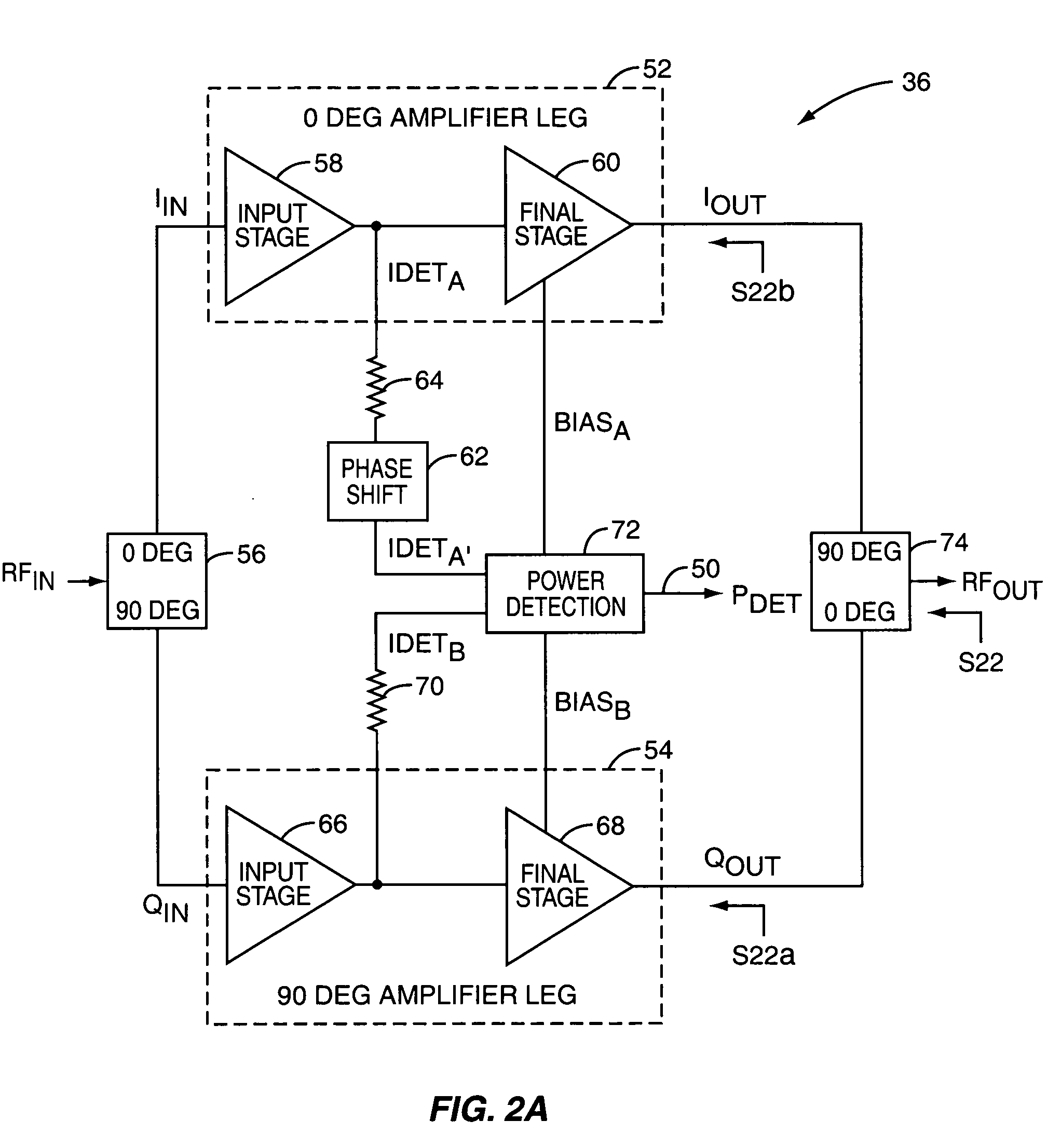
The present invention provides a system for detecting the output power of power amplifier circuitry in a mobile terminal. The system uses balanced power amplifier circuitry with in-phase and quadrature phase amplifier circuitry. A power detection system provides a power detection signal based on a measurable parameter that varies with power, such as current, in the final amplifier stage of both circuits. The system combines the amplified signals and detects the combined detect signal using detection circuitry that rectifies and filters the signal. The system also includes phase shift circuitry to adjust the phase of the in-phase detect signal to prevent signal amplitude reduction. The technical effect of the invention is to provide a reliable and accurate method for measuring the output power of power amplifier circuitry in a mobile terminal.

Problems solved by technology

However, in reality, there are variations in the load impedance due to variations in the impedance of the components in the transmit chain following the power amplifier, such as a duplexer, with frequency and temperature, and variations in the impedance of the antenna of the mobile terminal caused by proximity of the antenna to foreign metallic objects and the user's body.
Such output power variations decrease the quality of service (QoS), increase the probability of dropped calls in fringe areas, increase the liability of mobile terminal manufacturers in terms of tolerated output power versus Specific Absorption Ratio (SAR), and increase the peak current of the power amplifier.
However, the directional coupler is an additional component that adds loss to the transmit path, which reduces the efficiency of the mobile terminal, and increases the cost of manufacturing the mobile terminal.

Method used


Image

  • VSWR tolerant power detector
  • VSWR tolerant power detector
  • VSWR tolerant power detector

Examples


Embodiment Construction

[0015]The embodiments set forth below represent the necessary information to enable those skilled in the art to practice the invention and illustrate the best mode of practicing the invention. Upon reading the following description in light of the accompanying drawing figures, those skilled in the art will understand the concepts of the invention and will recognize applications of these concepts not particularly addressed herein. It should be understood that these concepts and applications fall within the scope of the disclosure and the accompanying claims.

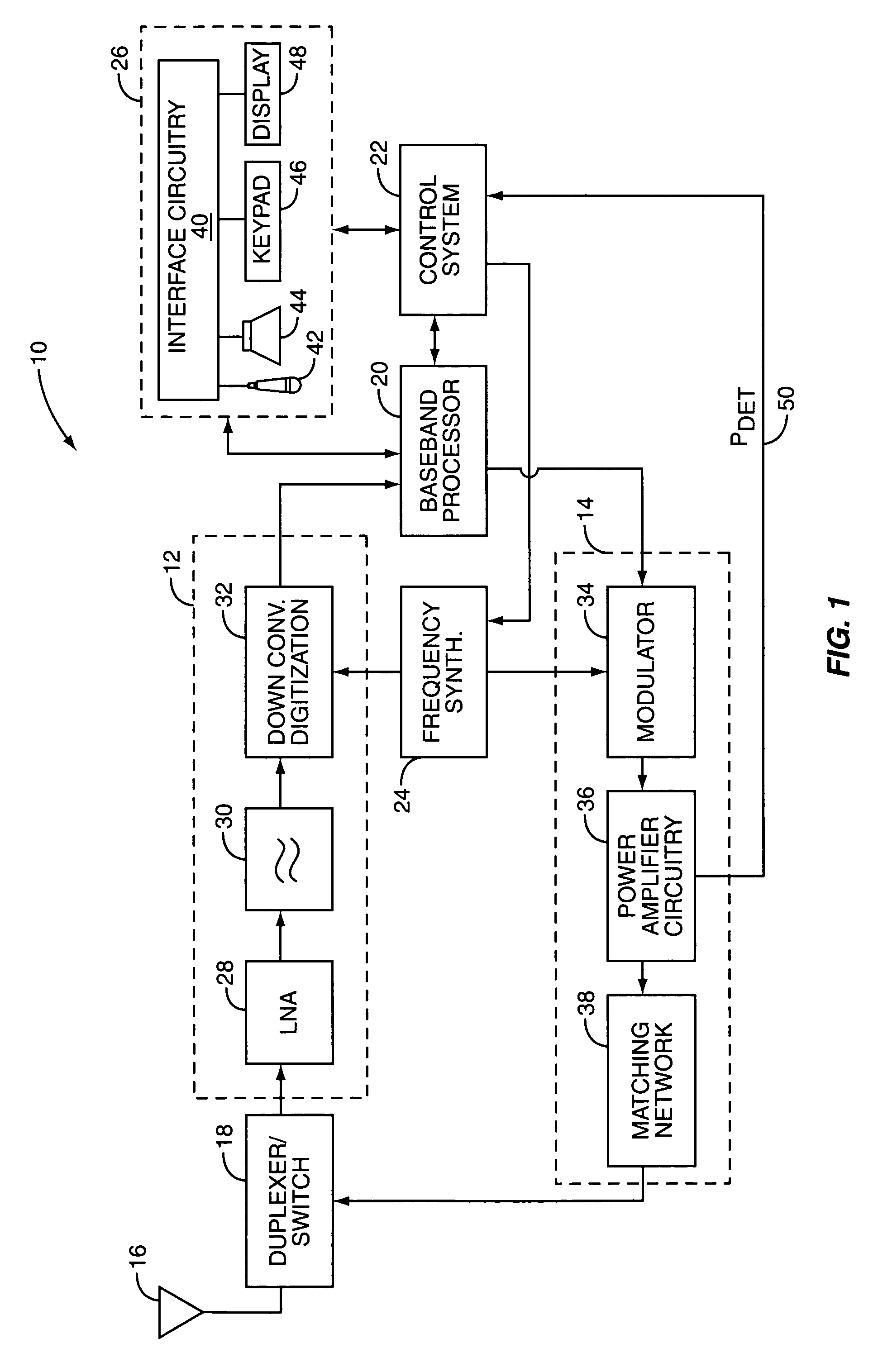
[0016]The present invention may be incorporated in a mobile terminal 10, such as a mobile telephone, wireless personal digital assistant, wireless Local Area Network (LAN) device, wireless base station, or like wireless communication device. The basic architecture of a mobile terminal 10 is represented in FIG. 1 and may include a receiver front end 12, a radio frequency transmitter section 14, an antenna 16, a duplexer or switch 1...


PUM


Abstract

A system is provided for detecting the output power of power amplifier circuitry in a transmitter of a mobile terminal. Balanced power amplifier circuitry is provided having in-phase power amplifier circuitry and quadrature phase amplifier circuitry. A power detection system provides a power detection signal indicative of the output power of the balanced power amplifier circuitry based on an in-phase detect signal indicative of some measurable parameter that varies with power, such as current, in a final amplifier stage of the in-phase amplifier circuitry and a quadrature phase detect signal indicative of some measurable parameter that varies with power, such as current, in a final stage of the quadrature phase amplifier circuitry.

Description

FIELD OF THE INVENTION[0001]The present invention relates to detecting the output power of a mobile terminal, and more specifically relates to a system for detecting the output power of a power amplifier in the transmit chain of the mobile terminal that is tolerant to variations in load impedance.BACKGROUND OF THE INVENTION[0002]The output power of mobile terminals, such as mobile phones, Personal Digital Assistants (PDAs), and the like, is controlled by a power amplifier in the transmit chain. For open loop power amplifiers, the output power of the power amplifier, and thus the mobile terminal, is a function of the load impedance seen at the output of the power amplifier. Ideally, the load impedance is a constant load. However, in reality, there are variations in the load impedance due to variations in the impedance of the components in the transmit chain following the power amplifier, such as a duplexer, with frequency and temperature, and variations in the impedance of the antenn...

Claims


Application Information

Patent Timeline
Patent Type & Authority Patents(United States)
IPC IPC(8): H03F3/68
CPCH03F1/0216H03F3/189H03F3/602
Inventor STOCKERT, TERRY
Owner QORVO US INC
Learn More