
Systems and methods for inspection of ophthalmic lenses

a technology for ophthalmic lenses and inspection systems, applied in the field of lens inspection systems, can solve the problems of contamination on the inspection window, fine defects in the lens, and the detection of fine defects, so as to reduce false rejection of inspected lenses, and improve the accuracy of lens inspection. the effect of detection accuracy

Active Publication Date: 2007-08-14
COOPERVISION INT LTD
View PDF22 Cites 15 Cited by
  • Summary
  • Abstract
  • Description
  • Claims
  • Application Information

AI Technical Summary

Benefits of technology

[0014]The edge and surface images of the ophthalmic lenses may be inspected separately and / or in combination. In the illustrated embodiment disclosed herein, the images are inspected by executing one or more computer programs that analyze changes in pixel intensity or contrast of the digitized images of the lenses. The combined results from the analysis of the lens images attempt to provide more accurate detection of lens defects, and attempt to reduce false rejections of the inspected lenses. For example, by combining results from each image of the lens, “noise”, which may seem to be a lens defect in an otherwise acceptable lens, is reduced or eliminated so that the lens is not rejected. In addition, by acquiring a plurality of images of the lens with a camera having a relatively narrow depth of field, each of the images is a high resolution image of the lens edge or lens surface, and thus, fine defects in the lens, including the lens edge and / or the center of the lens, may be detected, as well as, contamination on the inspection window near the lens edge. The software provided with the inspection system may also categorize the defects detected in or on the lens based on predefined criteria of such defects. For example, defects may be categorized based on the size, shape, or intensity of the image corresponding to the defect. The software provided with the inspection system may also be able to accurately track the lens edge with high resolution to be able to discriminate between debris that may be on the inspection window in proximity to the lens edge but not actually contacting the lens edge, and actual defects on or in the lens edge. In other words, the software of the system may permit debris that is in the light path of the inspection system and that is near the lens edge, but is not abutting the lens edge, to be detected. In additional embodiments, the system may also be able to detect differences in lens edge defects and debris that is contacting the edge of the lens.

Problems solved by technology

In addition, by acquiring a plurality of images of the lens with a camera having a relatively narrow depth of field, each of the images is a high resolution image of the lens edge or lens surface, and thus, fine defects in the lens, including the lens edge and / or the center of the lens, may be detected, as well as, contamination on the inspection window near the lens edge.

Method used


Image

  • Systems and methods for inspection of ophthalmic lenses
  • Systems and methods for inspection of ophthalmic lenses
  • Systems and methods for inspection of ophthalmic lenses

Examples


Embodiment Construction

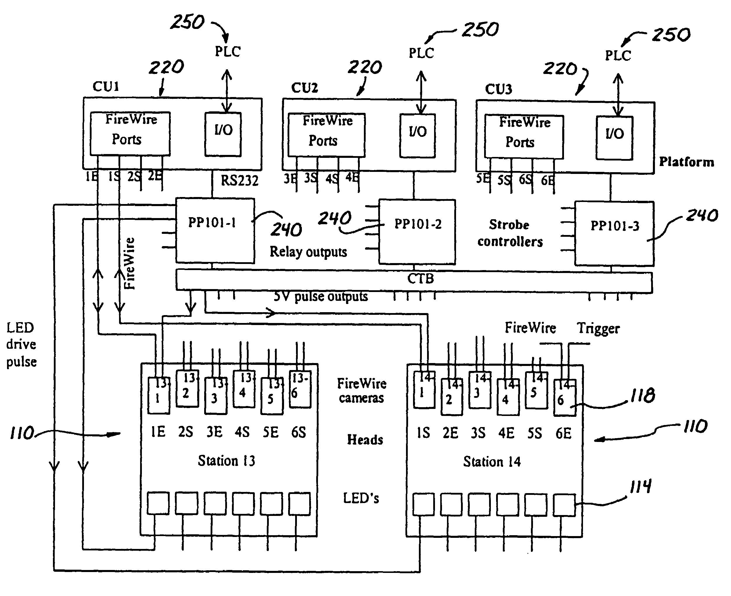
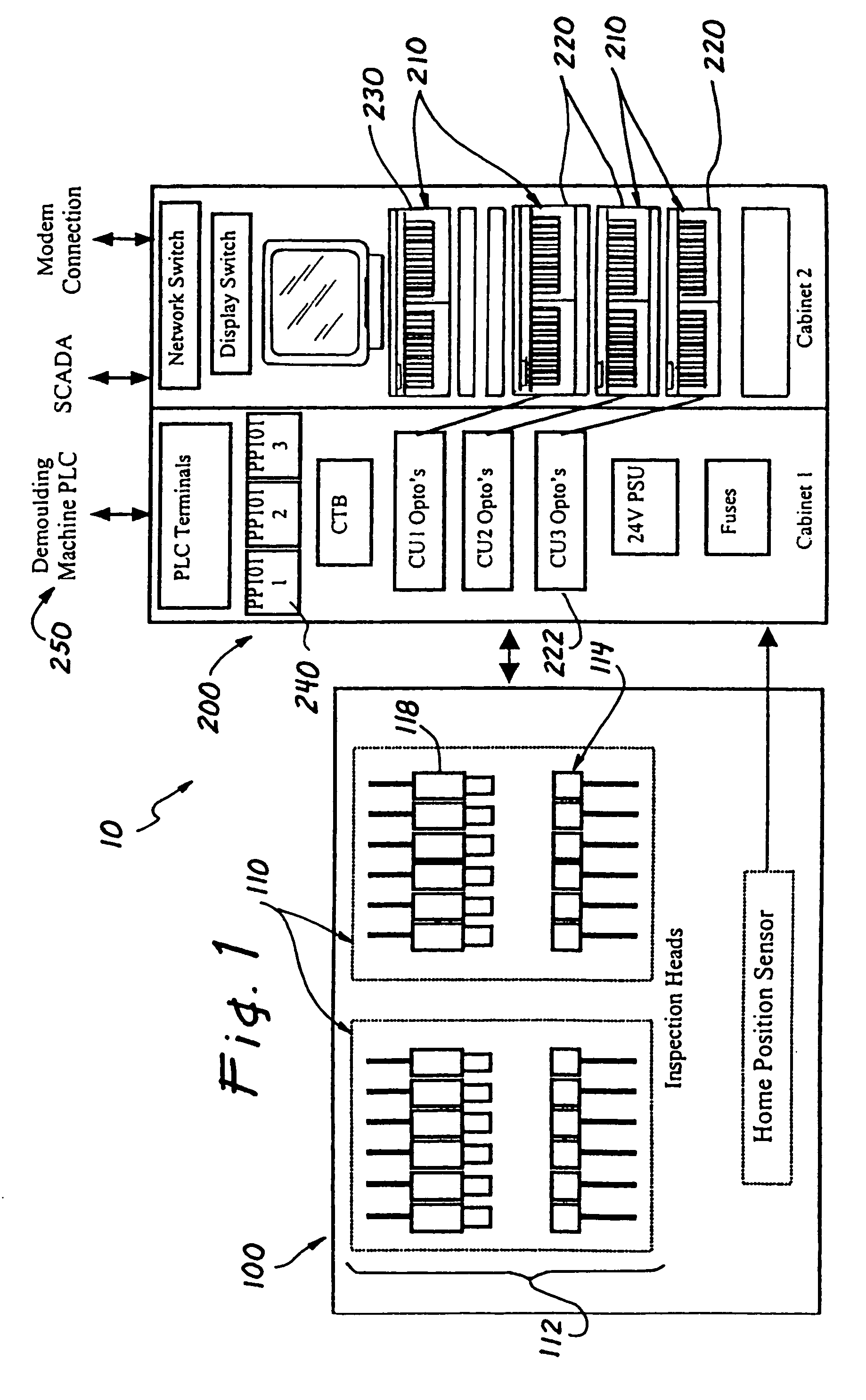
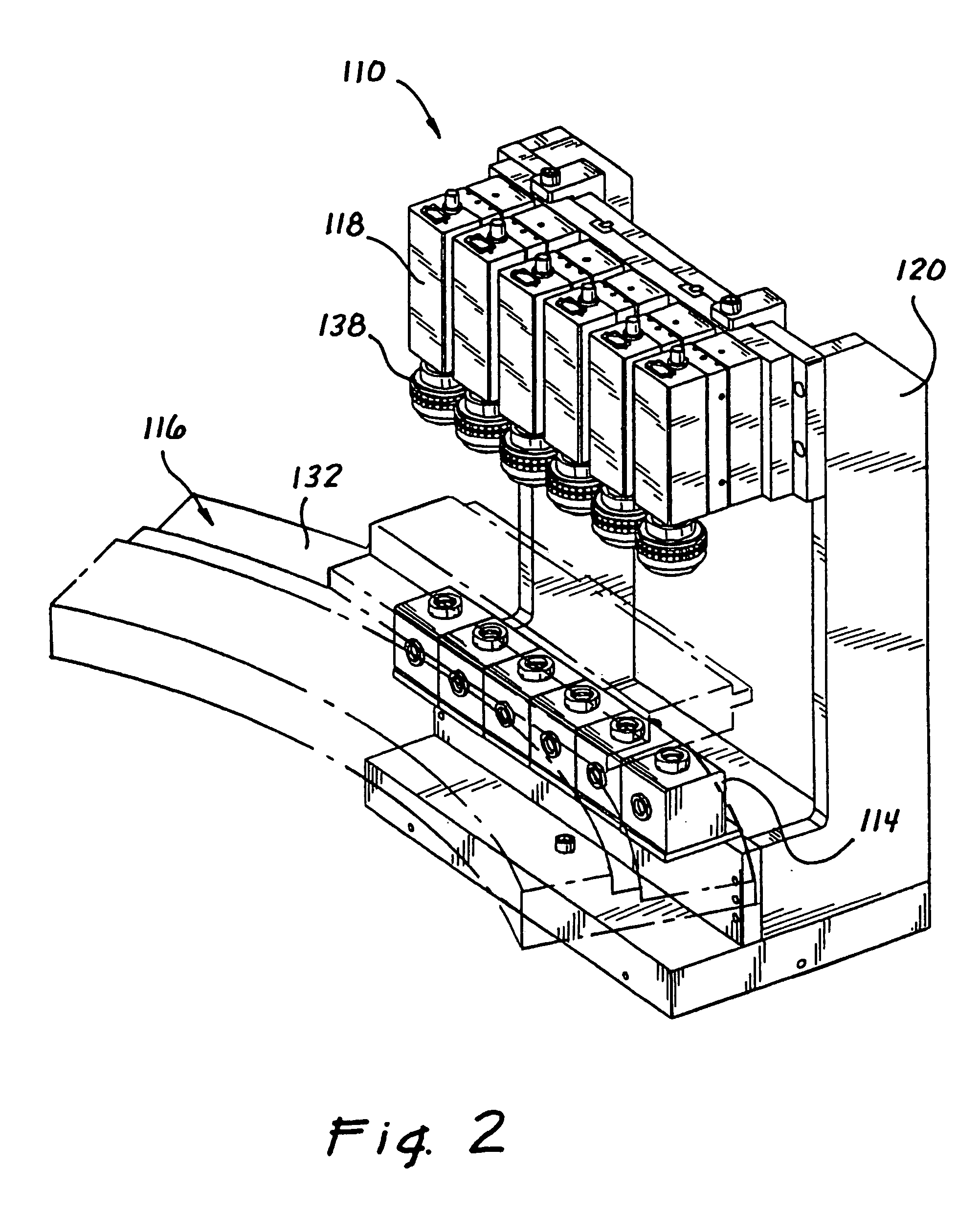
[0028]FIG. 1 illustrates a lens inspection system 10, which is used to automatically inspect lenses, such as contact lenses, or other ophthalmic lenses. Lens inspection system 10 is structured to inspect lenses in their dry, or non-hydrated, state. In the illustrated embodiment of the invention, lens inspection system 10 inspects each lens after the lens has been removed from a lens mold. The inspection system 10 inspects the lens by imaging the edge of the lens and imaging the surface of the lens, and processing the edge and surface images using one or more computer algorithms to detect lens defects or abnormalities.

[0029]Lens inspection system 10 generally comprises an image acquisition subsystem 100, and an image analysis subsystem 200. In reference to the disclosure herein, the image acquisition subsystem 100 may be an ophthalmic lens demolding machine, and the image analysis subsystem 200 may be referred to as an inspection platform.

[0030]1. Image Acquisition Subsystem 100.

[003...


PUM


Abstract

An automated lens inspection system that images the edge and surface of an ophthalmic lens transmits light through the ophthalmic lens to a camera to create a complete digital image of the lens edge or lens surface. The digitized image(s) is(are) analyzed to detect defects or abnormalities of the ophthalmic lens. Methods of inspecting ophthalmic lenses are also disclosed.

Description

CROSS-REFERENCE TO RELATED APPLICATIONS[0001]This application claims the benefit of U.S. Provisional Application Ser. No. 60 / 357,610, filed Feb. 15, 2002, the content of which in its entirety is hereby incorporated by reference.BACKGROUND OF THE INVENTION[0002]1. Field of the Invention[0003]The present invention relates to lens inspection systems, and more particularly, the invention relates to automated systems and methods for inspecting ophthalmic lenses by acquiring and analyzing a plurality of images of the lenses being inspected.[0004]2. Description of Related Art[0005]Precision and accuracy in manufacturing ophthalmic lenses, such as contact lenses, are crucial for the use of such lenses in patients. Due to the increased demand for contact lenses, the manufacturing process of contact lenses has been automated to reduce manufacturing time and increase product turnover. However, the contact lenses are susceptible to damage, abnormalities, or contamination that would make the len...

Claims


Application Information

Patent Timeline
IPC IPC(8): G01B9/00G01BG01B1/00G01N21/85G01M11/00G01M11/02G02C13/00G06K9/00
CPCG01M11/0214G01M11/0278G01M11/0242G01M11/0235G01B9/00G01M11/00
Inventor LEPPARD, KIRKHOYLE, MARKTOWNSEND, CHRISHAZEL, MIKE
Owner COOPERVISION INT LTD
Learn More