Suction unit for use in an electric vacuum cleaner and electric vacuum cleaner employing same

a technology of vacuum cleaner and suction unit, which is applied in the direction of vacuum cleaners, brushes, carpet cleaners, etc., can solve the problems of danger of electrocution and fire, and achieve the effect of improving usability and enhancing dust collection

Inactive Publication Date: 2007-08-21
PANASONIC CORP
View PDF4 Cites 7 Cited by
  • Summary
  • Abstract
  • Description
  • Claims
  • Application Information

AI Technical Summary

Benefits of technology

[0004]It is, therefore, an object of the present invention to provide a safe and simple electric vacuum cleaner capable of continuously providing large quantities of negative ions to enhance dust collection and improve usability thereof.

Problems solved by technology

However, conventional negative ion generating devices employing electric discharge have drawbacks while generating negative ions such as generation of byproducts such as harmful ozone and a high voltage circuit for generating electric discharge employed therein poses a danger of electrocution and a fire.

Method used


Image

  • Suction unit for use in an electric vacuum cleaner and electric vacuum cleaner employing same
  • Suction unit for use in an electric vacuum cleaner and electric vacuum cleaner employing same
  • Suction unit for use in an electric vacuum cleaner and electric vacuum cleaner employing same

Examples


embodiment i

[0020]Hereinafter, a first embodiment of the present invention will now be described in detail with reference to FIGS. 1 to 9.

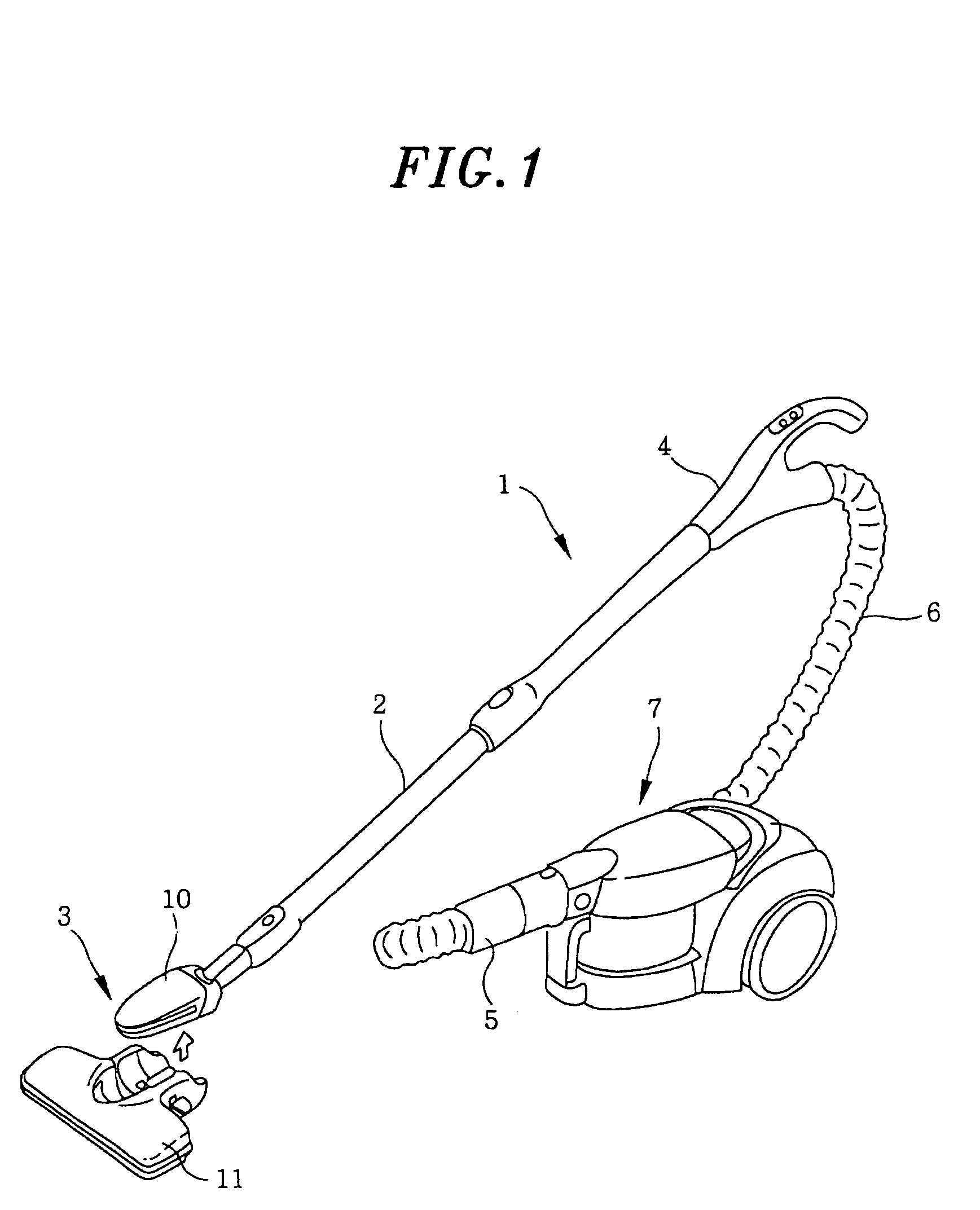
[0021]As illustrated in FIG. 1, the preferred embodiment pertains to a canister type electric vacuum cleaner 1 and a suction unit 3 serving as a suction inlet. The suction unit 3 is detachable provided at a distal end portion of an extension tube 2 that is coupled with a handle (control unit) 4. Hose 6 coupled with handle 4 is connected to the main body 7 of the electric vacuum cleaner 1 via hose joint 5.

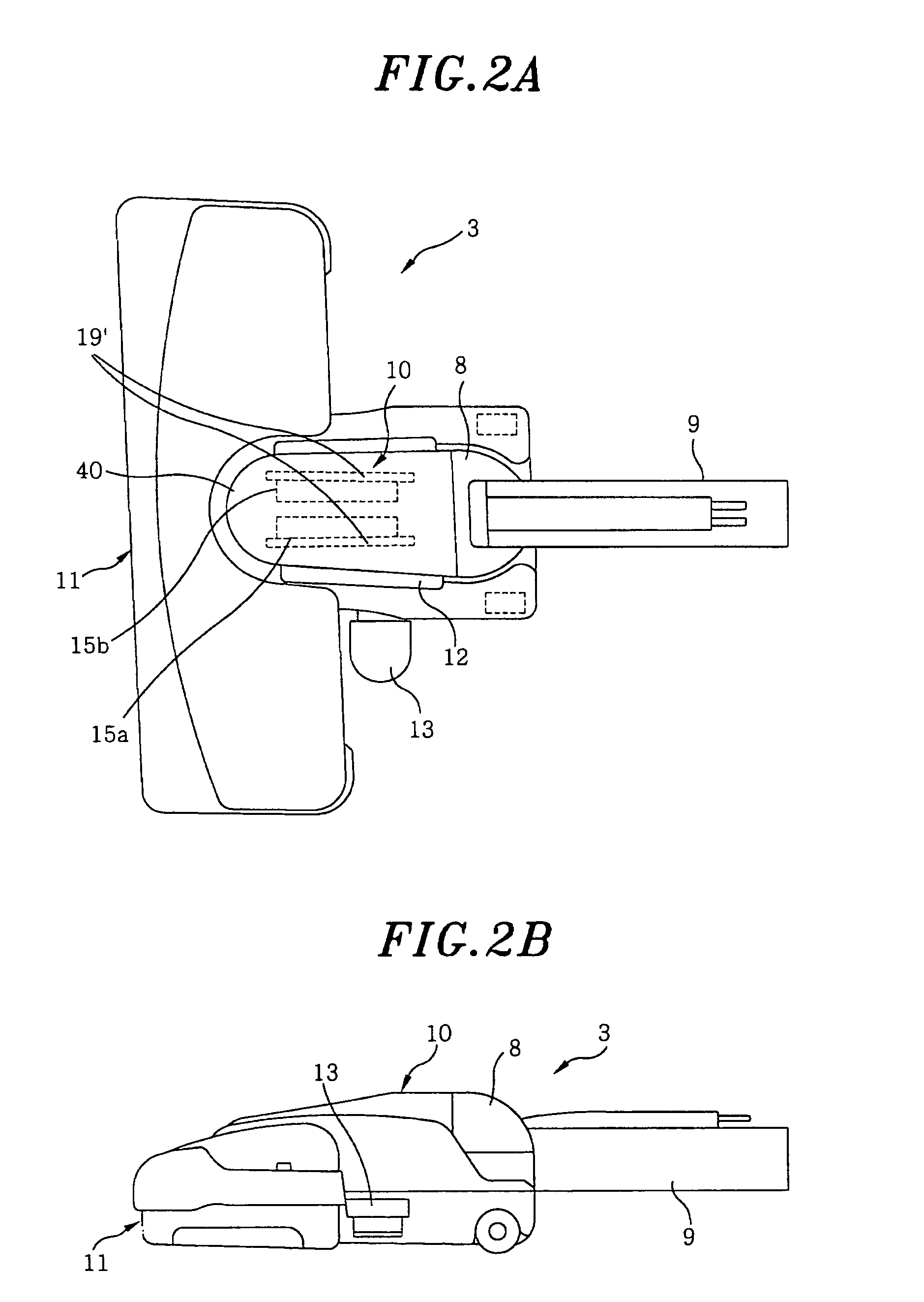
[0022]Suction unit 3 as illustrated in FIGS. 2A and 2B, includes floor nozzle 11 and mini nozzle 10 to be detachably secured onto floor nozzle 11. Mini nozzle 10 incorporates connection tube (connection portion) 9 to be connected with extension tube 2; and rotatable joint 8 (means for rotatable jointing) which at a front portion thereof is rotatably connected with suction head 40 of mini nozzle 10 and at a rear portion thereof is connected with connection tub...

embodiment ii

[0046]A second preferred embodiment in accordance with the present invention will now be described with reference to FIGS. 10 and 11. Parts that are substantially identical to those shown above will be assigned with the same reference numerals and the description thereof will be omitted.

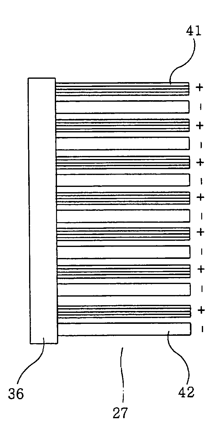
[0047]A portion from lower side faces of mini nozzle 10 to bottom 22 is formed in an arc shape and is provided with a plurality of openings 23 as shown in FIG. 10. At a bottommost peak portion along the axis bristles 27 made up of bristle members having different relative charge affinity as shown in FIG. 11 is provided on a sheet of base fabric 36 and there are provided openings 23 at both lateral sides thereof, having bristles 27 at respective sides thereof.

[0048]Hereinafter, an operation of the above-described configuration will be described.

[0049]When vacuum cleaning, bristles 27 come in contact with a surface to be cleaned, creating a friction therebetween, at which time bristle members 41 and 42...


PUM


Abstract

A suction unit for use in an electric vacuum cleaner and an electric vacuum cleaner includes a floor nozzle and a mini nozzle detachably secured to the floor nozzle. When a suction head of the mini nozzle is secured to the floor nozzle, an air communication is provided therebetween. Further, the mini nozzle is provided with an ion generating unit.

Description

FIELD OF THE INVENTION[0001]The present invention relates to a suction unit for use in electric vacuum cleaners for sucking in dirt particles and an electric vacuum cleaner using same.BACKGROUND OF THE INVENTION[0002]In conventional negative ion generating devices, negative ions are generated by applying a high voltage generated by a high voltage circuit to separated electrodes, and as a result generating electric discharge via an air pocket interposed therebetween; by emitting electrons of negative charges in the air through electric discharge at a surface of insulator between electrodes which in turn negatively charges water vapors and etc. in the air; or by irradiating surfaces of gold or platinum with ultraviolet ray to emit electrons in the metal to the air which in turn negatively charges the water vapors and etc. in the air. (see, for example, Japanese Patent Laid-open No. 2001-338744)[0003]However, conventional negative ion generating devices employing electric discharge hav...

Claims


Application Information

Patent Timeline
Patent Type & Authority Patents(United States)
IPC IPC(8): A47L13/40A46B15/00A47L9/02A47L9/04A47L9/06A47L9/24
CPCA47L9/02A47L9/06A47L9/0613A47L9/242
Inventor SHIBUYA, MASAKIFUJITA, KOICHISOEJIMA, MASAKUNI
Owner PANASONIC CORP
Why Eureka
Try Eureka