Debris filter with a rotating debris extractor

a technology of debris filter and extractor, which is applied in the direction of gravity filter, loose filtering material filter, sedimentation settling tank, etc., can solve the problems of large water quantity, waste of resources, and waste of resources, and the need for debris removal and periodic removal posses a serious challenge to power generating plants

Inactive Publication Date: 2007-08-21
GEA ENERGY SYST INDIA
View PDF12 Cites 25 Cited by
  • Summary
  • Abstract
  • Description
  • Claims
  • Application Information

AI Technical Summary

Benefits of technology

[0007]The profile of the debris extractor arm provides a suction effect right through the arm. That is to say the suction is created on the entire length of arm. The debris extractor arm has a specially designed profile with a curvature towards the screen extending outwards at a predetermined radius with respect to vertical plane. This profile causes a lower pressure between the screen and the extractor compared to pressure elsewhere in the screen. This feature ensures that the debris on the screen is lifted from the screen and channeled through the extractor to the outlet. The modified design of debris extractor of the present invention overcome the constraints of the debris filter known in the prior art, resulting in higher efficiency and better performance of the debris filter.
[0009]Yet another object of the invention is to provide a debris filter with debris extractor which does not disturb the smooth rotation of debris extraction arm.
[0010]A further object of the invention is to provide a sturdy debris filter with a debris extractor which is efficient, economical and avoid the need for a water jet spray arrangement to clean the inside of the basket.

Problems solved by technology

The quantity of water required is quite large and it contains debris like grass, shells, fish, cloth and plastic sheet.
These debris tend to clog the tubes of the steam condensers causing reduction in heat transfer which in turn may affect power generation.
The problem of accumulation of debris and need for periodic removal of debris posses a serious challenge to the power generating plants.
The disadvantages faced by using this filter is that the sealing lips near the location where the suction arm closes a segment of the screen to create back wash, wears off and thereby back wash effect reduces time to time.
Further the debris coming between the seal and suction arm obstructs the smooth rotation of the suction arm.
In this debris filter the profile of the debris extractor does not facilitate removal of sticky debris from the screen easily.
This arrangement results in additional power consumption for the water spray pump and also makes it more expensive.

Method used


Image

  • Debris filter with a rotating debris extractor
  • Debris filter with a rotating debris extractor
  • Debris filter with a rotating debris extractor

Examples


Embodiment Construction

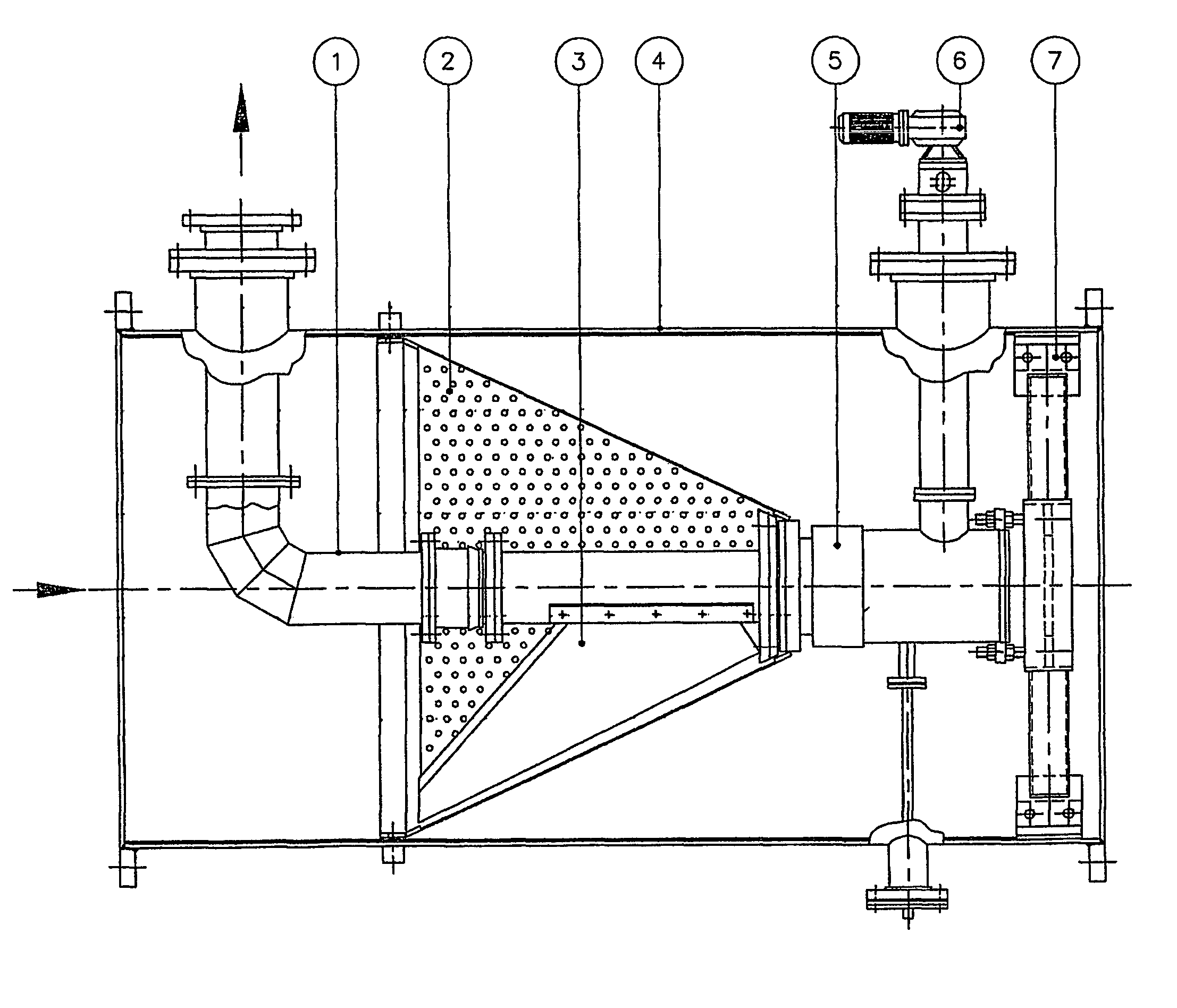
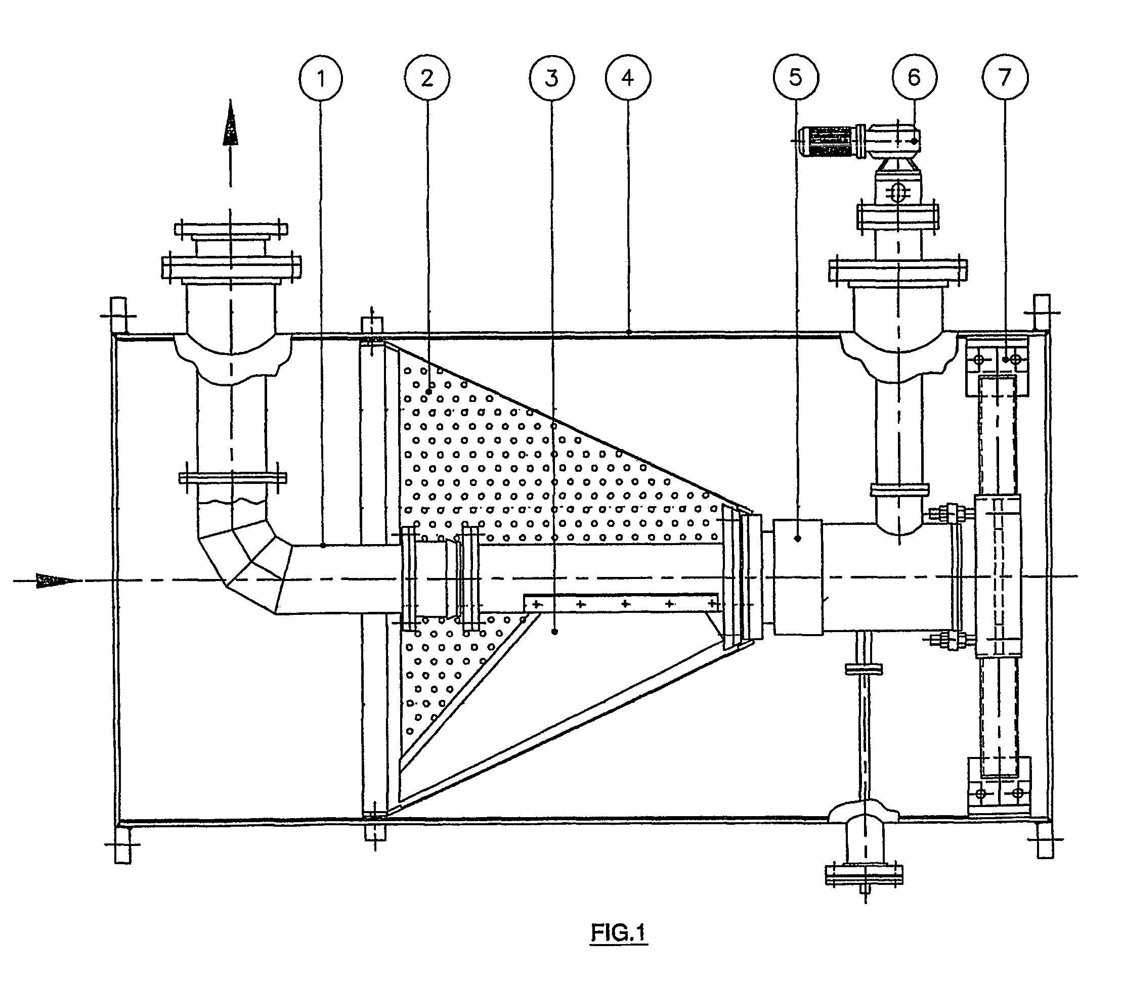
[0019]The debris filter according to the invention comprises a screen basket (2) which captures the debris, a debris discharge pipe (1), to discharge the accumulated and captured debris, a debris extractor arm (3) for removing debris from the screen basket (2), all housed in a tubular housing (4). Then the debris extractor arm (3) is rotated at low speed preferably using geared motor drive (6). A special gear train may be incorporated in the gear box housing (5) to enable high torque at minimum speed. The gear box housing (5) and gear box sealing support (7) are housed in a housing (4) and the debris extractor arm (3) is rotated by a motor drive (6).

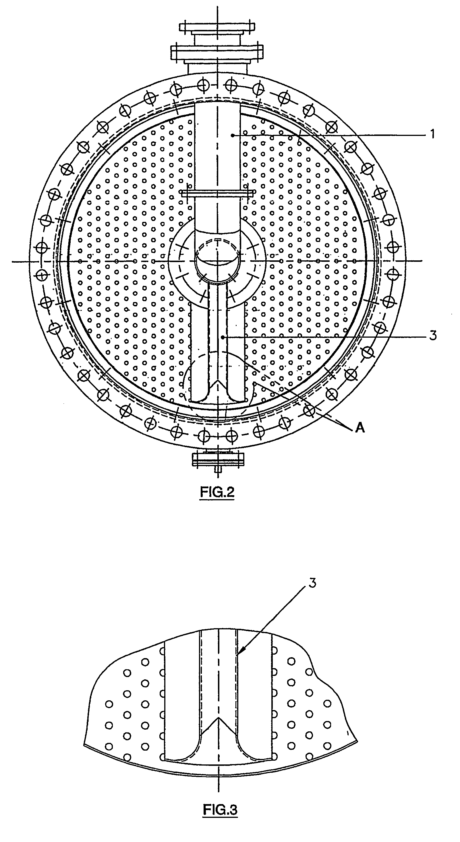
[0020]The debris extractor arm (3) does not come in contact with screen but at the same time produces an effective extraction of debris from the screen basket (2). In addition, it eliminates the problems in the debris separators known in the art and avoids use of a prevalent special water spray pump. This is achieved by a unique profile ...


PUM

PropertyMeasurementUnit
perforation sizeaaaaaaaaaa
inlet flow velocitiesaaaaaaaaaa
lengthaaaaaaaaaa

Abstract

A filter for filtering solid particles from liquids, especially for use in steam condensers and heat exchanger in thermal and nuclear power plants, said filter comprising a housing (4), a screen basket (2) located within said housing (4), a debris discharge pipe (1) for discharging accumulated and captured debris; a debris extractor arm (3) with a curvature towards the screen extending outwards at a predetermined radius with respective vertical plane, the said debris extractor arm (3) being rotatably driven over the entire length of the screen to create a low pressure between the debris extractor arm (3) and the screen (4) for complete extraction of debris and conveying to said debris discharge pipe (1).

Description

FIELD OF INVENTION[0001]This invention relates to a debris filter with rotating debris extractor. In particular, this invention is concerned with a debris extractor. Further, this invention provides a system and a method, of removal of debris from filter screen.BACKGROUND OF THE INVENTION[0002]It is well known in the art that thermal and nuclear power plants use steam condensers for condensation of steam after the energy has been utilized to drive the turbine. The steam condensers known in the art may be either water-cooled or air-cooled. In water-cooled process, water is typically obtained from sources like sea, rivers and lakes. The quantity of water required is quite large and it contains debris like grass, shells, fish, cloth and plastic sheet. These debris tend to clog the tubes of the steam condensers causing reduction in heat transfer which in turn may affect power generation. The problem of accumulation of debris and need for periodic removal of debris posses a serious chall...

Claims


Application Information

Patent Timeline
Patent Type & Authority Patents(United States)
IPC IPC(8): B01D29/68G21D1/00B01D29/11B01D29/35B01D29/62G21F9/06
CPCB01D29/35B01D29/6476B01D2201/02B01D2201/082
Inventor RAGHUPATHY, BALAKRISHNAN GOVINDASAMY
Owner GEA ENERGY SYST INDIA
Why Eureka
Try Eureka