Backlight unit including curved fluorescent lamp, and liquid crystal display apparatus including the backlight unit

a backlight unit and fluorescent lamp technology, applied in lighting and heating apparatus, instruments, and in the direction of light, can solve the problems of uneven temperature distribution of the backlight unit, inability to achieve a thin body, and difference in brightness between fluorescent lamps, so as to achieve the effect of restricting brightness

Active Publication Date: 2007-08-21
GK BRIDGE 1
View PDF8 Cites 6 Cited by
  • Summary
  • Abstract
  • Description
  • Claims
  • Application Information

AI Technical Summary

Benefits of technology

[0015]With the above-stated construction in which the curved fluorescent lamp is arranged so that the electrodes are at low positions and the folded portion is at a high position in the outer container when the backlight unit is erected vertically in use, the heat generated by the electrodes, which are the main heat source, flows upwards in the glass bulb, and most of the heat is used to heat a rare gas that is usually filled in the glass bulb. When this happens, the gas (the air) filling the backlight unit is not heated as much as in conventional backlight units. This restricts the temperature rise in the backlight unit, and reduces the unevenness in temperature distribution in the backlight unit in the vertical direction. This construction, therefore, restricts the unevenness in brightness in the backlight unit, which is caused by the unevenness in temperature distribution.
[0016]Also, in the above-stated construction, the inverter, which is a meaning less heat source, is disposed outside the outer container. This restricts the unevenness in brightness in the overall backlight unit, which is caused by the unevenness in temperature due to the presence of the inverter in the outer container.

Problems solved by technology

In general, edge-light type backlight units are advantageous in achieving a thin body and even brightness on the light-emitting surface, but are disadvantageous in achieving high brightness, and the direct-below-type backlight units are advantageous in achieving high brightness, but are disadvantageous in achieving a thin body.
This causes the temperature distribution in the backlight unit to be more uneven.
This makes a difference in brightness between fluorescent lamps and causes uneven brightness in the overall backlight unit.
This causes uneven brightness in the overall backlight unit.

Method used


Image

  • Backlight unit including curved fluorescent lamp, and liquid crystal display apparatus including the backlight unit
  • Backlight unit including curved fluorescent lamp, and liquid crystal display apparatus including the backlight unit
  • Backlight unit including curved fluorescent lamp, and liquid crystal display apparatus including the backlight unit

Examples


modification 1

[0084]FIG. 9A is a partial plan view of a backlight unit 70 in Modification 1. FIG. 9B is an enlarged sectional view taken substantially along line B-B of FIG. 9A.

[0085]The backlight unit 70 in Modification 1 basically has the same construction as the backlight unit 2 in the above-described embodiment, except that it additionally includes heat releasing members 72. Accordingly, the members of the backlight unit 70 that have the same constructions as those of the backlight unit 2 are assigned the same reference numbers, and the description thereof is omitted here. The following description centers on the heat releasing members 72.

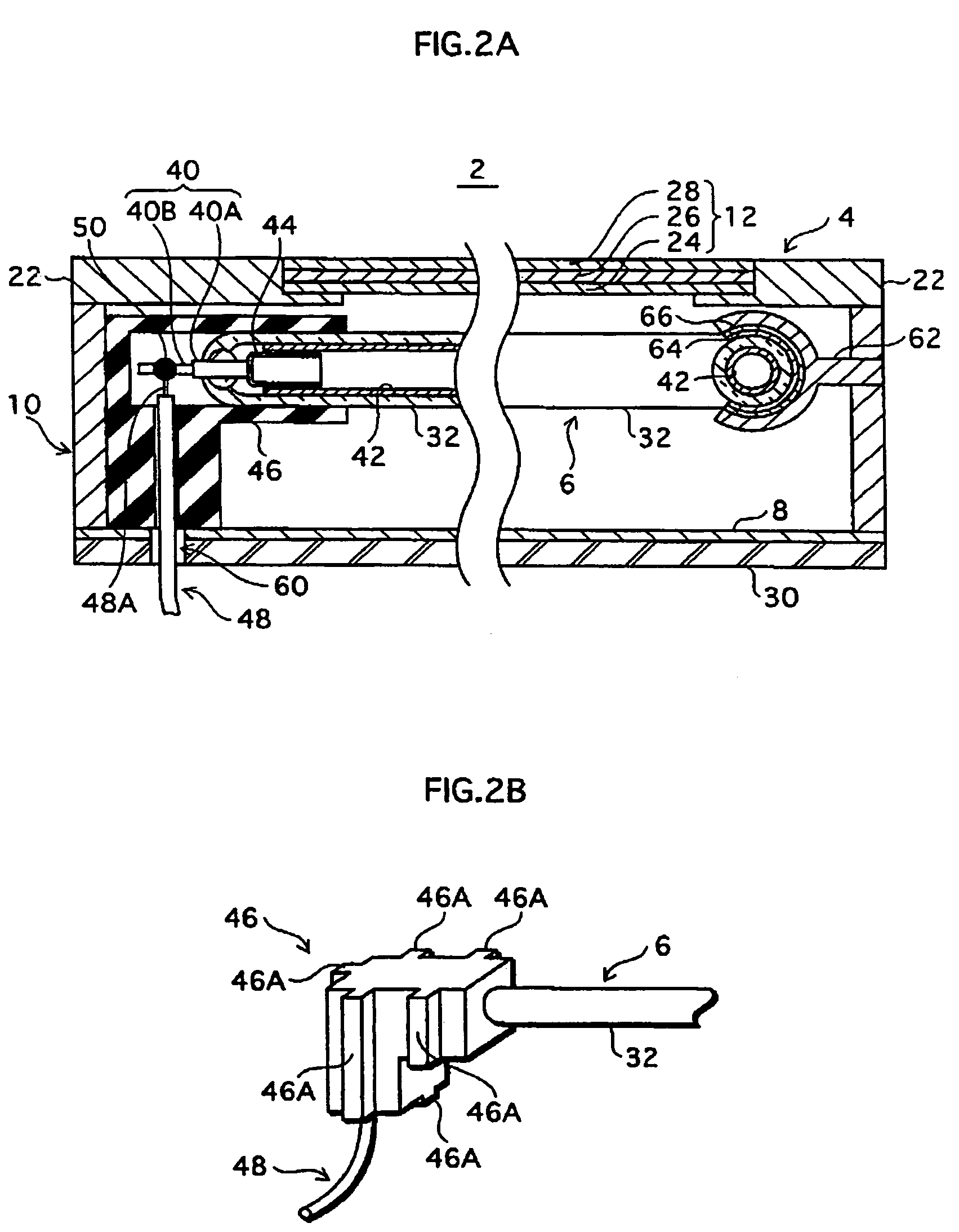
[0086]The heat releasing members 72 literally play a role of heat releasing members, and effectively release part of the heat that is generated by the fluorescent lamps 6, from the fluorescent lamps 6. The heat releasing members 72 also function as supporting members that support the fluorescent lamps 6 in the backlight unit, as shown in FIG. 9B.

[0087]Each h...

modification 2

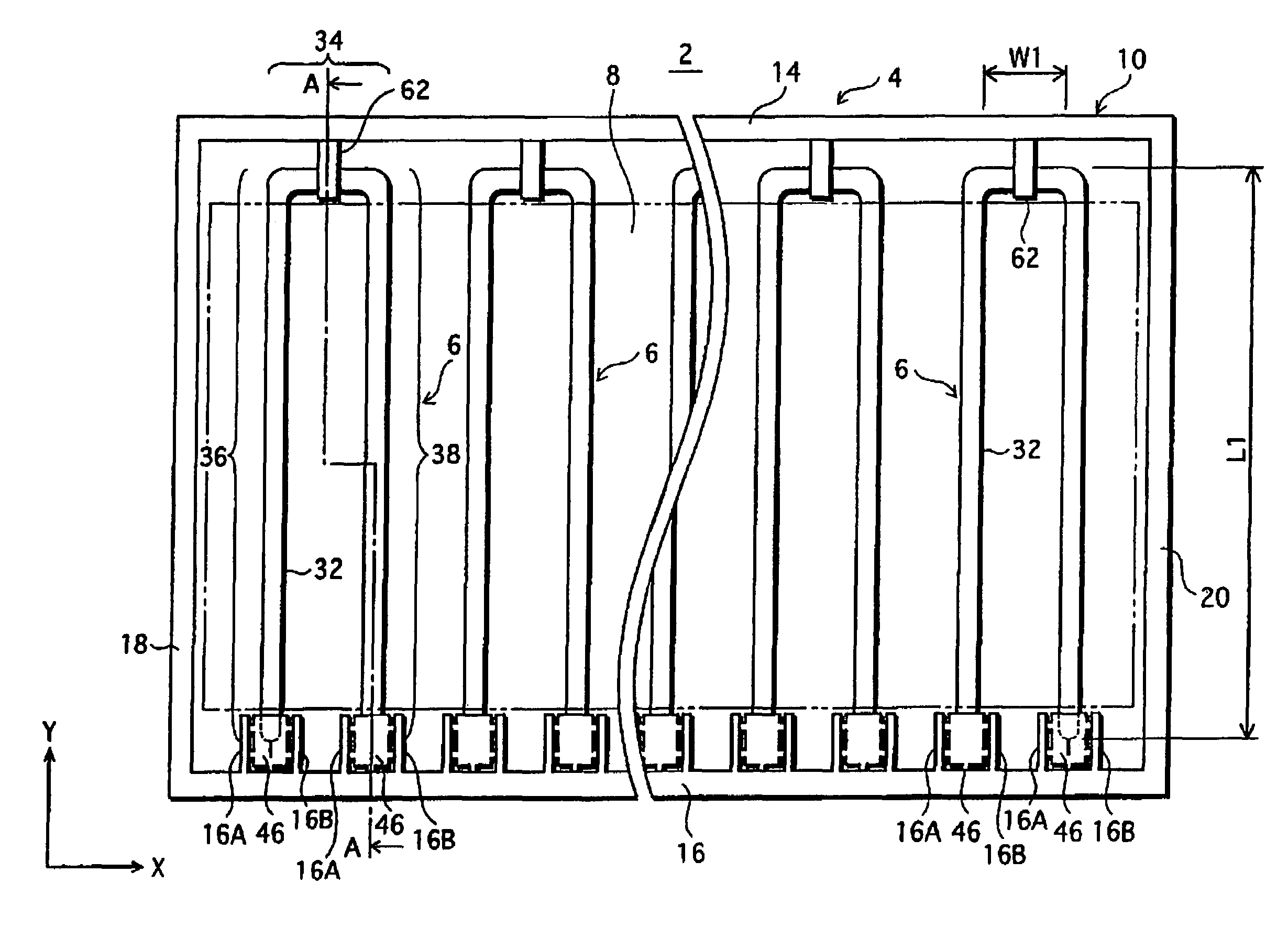
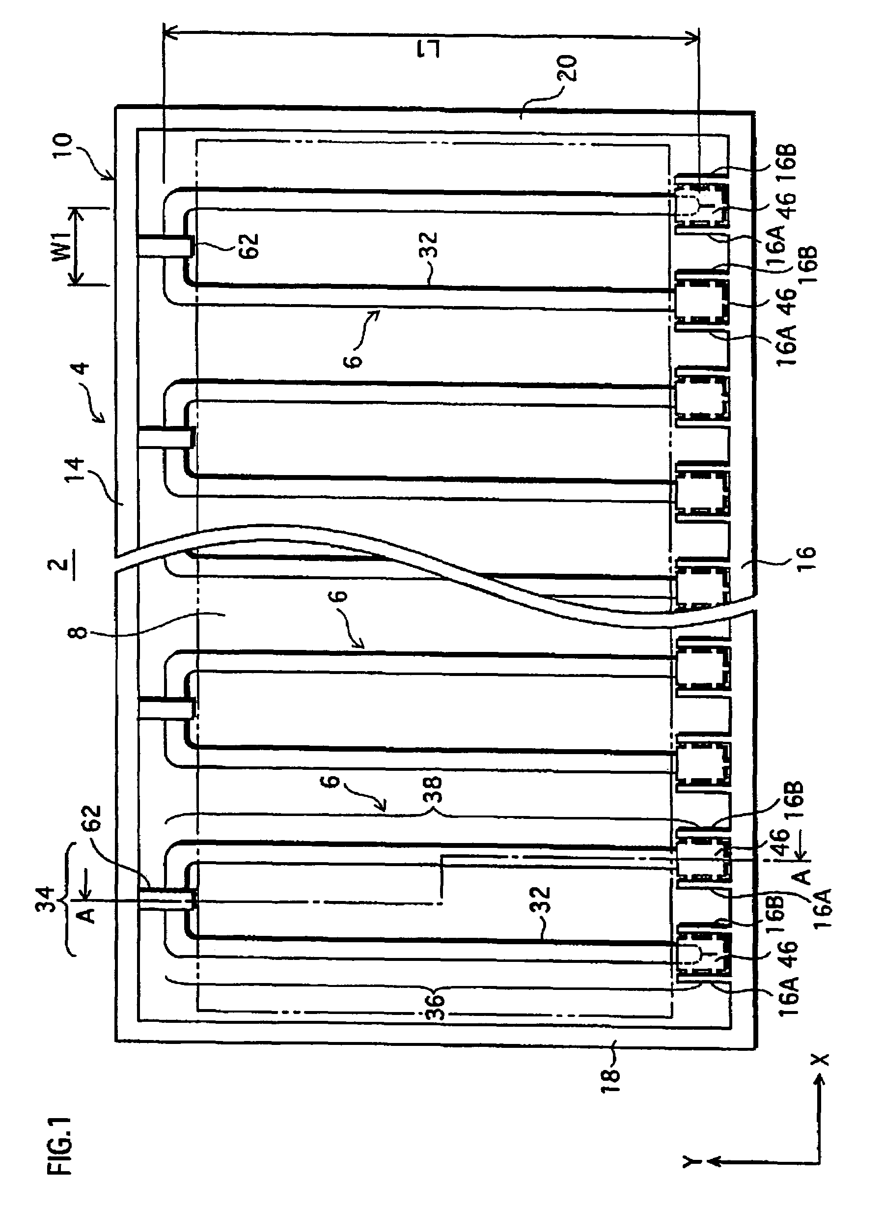
[0091]FIG. 10 is a partial plan view of a backlight unit 80 in Modification 2. The backlight unit 80 in Modification 2 basically has the same construction as the backlight unit 70 in Modification 1, except that it includes, instead of the a folded portion supporting member 62 (see FIG. 9A), straight-portion supporting members 82 which are each composed of a pair of supporting members 82A and 82B. Accordingly, the members of the backlight unit 80 that have the same constructions as those of the backlight unit 70 are assigned the same reference numbers, and the description thereof is omitted here. The following description centers on the differences.

[0092]As described above, in the backlight unit 80, the folded portion 34 is indirectly supported as the straight portions 36 and 38 are supported by the straight-portion supporting members 82. With this construction, compared with the case in which the folded portion 34 is directly supported by the folded portion supporting member 62, the...


PUM

PropertyMeasurementUnit
temperaturesaaaaaaaaaa
temperatureaaaaaaaaaa

Abstract

A backlight unit that includes: an outer container; a curved fluorescent lamp that is contained in the outer container and includes two electrodes and a glass bulb that has (i) a folded portion and (ii) two straight portions that extend in parallel with each other from the folded portion, and the two electrodes being respectively attached to two ends of the glass bulb; and an inverter operable to supply power for lighting to the curved fluorescent lamp. The inverter is disposed outside the outer container, and the curved fluorescent lamp is arranged so that the electrodes are at low positions and the folded portion is at a high position in the outer container when the backlight unit is erected vertically in use.

Description

[0001]This application is based on an application No. 2004-128940 filed in Japan, the contents of which are hereby incorporated by reference.BACKGROUND OF THE INVENTION[0002](1) Field of the Invention[0003]The present invention relates to a backlight unit and a LCD (Liquid Crystal Display) apparatus, especially to a backlight unit which is disposed at the back of a LCD panel to constitute a LCD apparatus, and to the LCD apparatus including the backlight unit.[0004](2) Description of the Related Art[0005]In recent years, as the LCD apparatuses have started to be employed in liquid crystal televisions or the like in full scale, the demand for the backlight units, which are mounted in the LCD apparatuses, has increased as well.[0006]Backlight units are classified into two types: an edge-light type (also referred to as a side-light type or an optical waveguide type) in which an optical waveguide is disposed on the back surface of a LCD panel, and fluorescent lamps are arranged at the ed...

Claims


Application Information

Patent Timeline
Patent Type & Authority Patents(United States)
IPC IPC(8): F21S4/00F21K2/00G02F1/1335G02F1/13357
CPCG02F1/133604G02F2001/133612G02F1/133612A63H33/28
Inventor YAMASHITA, HIROFUMITERADA, TOSHIHIROMANIWA, TAKASHIMORI, YUSUKE
Owner GK BRIDGE 1
Why Eureka
Try Eureka