Gathering and pressing device for a folded box-gluing machine

a box gluing machine and pressing device technology, applied in the field of gathering and pressing devices for folded box gluing machines, can solve the problems of short braking time and acceleration time, limited production speed, etc., and achieve the effect of increasing production speed and high quality

Active Publication Date: 2007-08-21
MASTERWORK GROUP CO LTD
View PDF15 Cites 4 Cited by
  • Summary
  • Abstract
  • Description
  • Claims
  • Application Information

AI Technical Summary

Benefits of technology

[0005]It is accordingly an object of the invention to provide a gathering and pressing device for a folded box-gluing machine which overcomes the above-mentioned disadvantages of the prior art devices of this general type, by which even complicated box types can be produced at an increased production speed and with high quality.
[0008]This solution with highly dynamic drives permits a higher production speed with a high product quality, since the drives can be braked and accelerated more quickly and, in addition, can be operated with a speed difference. Very short braking times and acceleration times are necessary if individual blanks have previously been removed from the machine by ejection systems, for example because they are faulty. In order to close the gaps produced when a blank is ejected, to produce a constant overlapping stream, which the following automatic packing machine requires, the conveyor belts have to be braked briefly and then accelerated again. In the case of the known drive, this leads to considerable loadings on the mechanical elements, so that the production speed is limited.
[0009]As a result of the lack of the connecting chain, during the braking and acceleration the pressurized displacement of the upper conveyor belt toward the lower conveyor belt is dispensed with and, in addition, the wear is reduced considerably. This makes it possible to increase the maximum speed of the conveyor belts by about 50% to about 60 m / min. Furthermore, it has been shown that, in the case of the known conveyor belts with a rigidly coupled drive, impairment of the quality in the finished products can occur. The lower, compliantly mounted conveyor belt gives way downward under the applied pressure. As a result of giving way, the lower conveyor belt has to some extent to cover a longer distance than the upper conveyor belt. Since, on account of the rigid coupling, the conveying speeds are the same, a stress is built up which leads to box parts delivered lying exactly one above another being displaced with respect to each other. According to the invention, the drives of the two conveyor belts can preferably be regulated relative to each other via a common control device. It is thus possible for a speed difference to be set between the upper conveyor belt and the lower conveyor belt, in order to avoid mutual displacement of box parts.
[0011]This makes it possible to act uniformly with pressure on the types of blank which have a different number of layers in the glued region and are configured asymmetrically. In the case of asymmetrical blanks, which are not uniformly thick over the width of the conveyor belts, the supporting rollers can be set somewhat obliquely. This prevents the pressure being applied only at the thickened points of the blanks.
[0013]The ability of each inlet gap to be adjusted individually makes it possible to brake the blanks, arriving with high momentum, without rotation. For this purpose, each inlet gap can be set as a function of the type of blank. Since, when the machine speed is changed, the momentum force likewise changes, the inlet gaps have to be corrected during the running production process, in order that the blanks are braked without rotation. The motorized adjustment from outside is more convenient for the operator and the risk of accidents is reduced drastically, since it is no longer necessary to reach into a running machine.

Problems solved by technology

Very short braking times and acceleration times are necessary if individual blanks have previously been removed from the machine by ejection systems, for example because they are faulty.
In the case of the known drive, this leads to considerable loadings on the mechanical elements, so that the production speed is limited.

Method used


Image

  • Gathering and pressing device for a folded box-gluing machine
  • Gathering and pressing device for a folded box-gluing machine
  • Gathering and pressing device for a folded box-gluing machine

Examples


Embodiment Construction

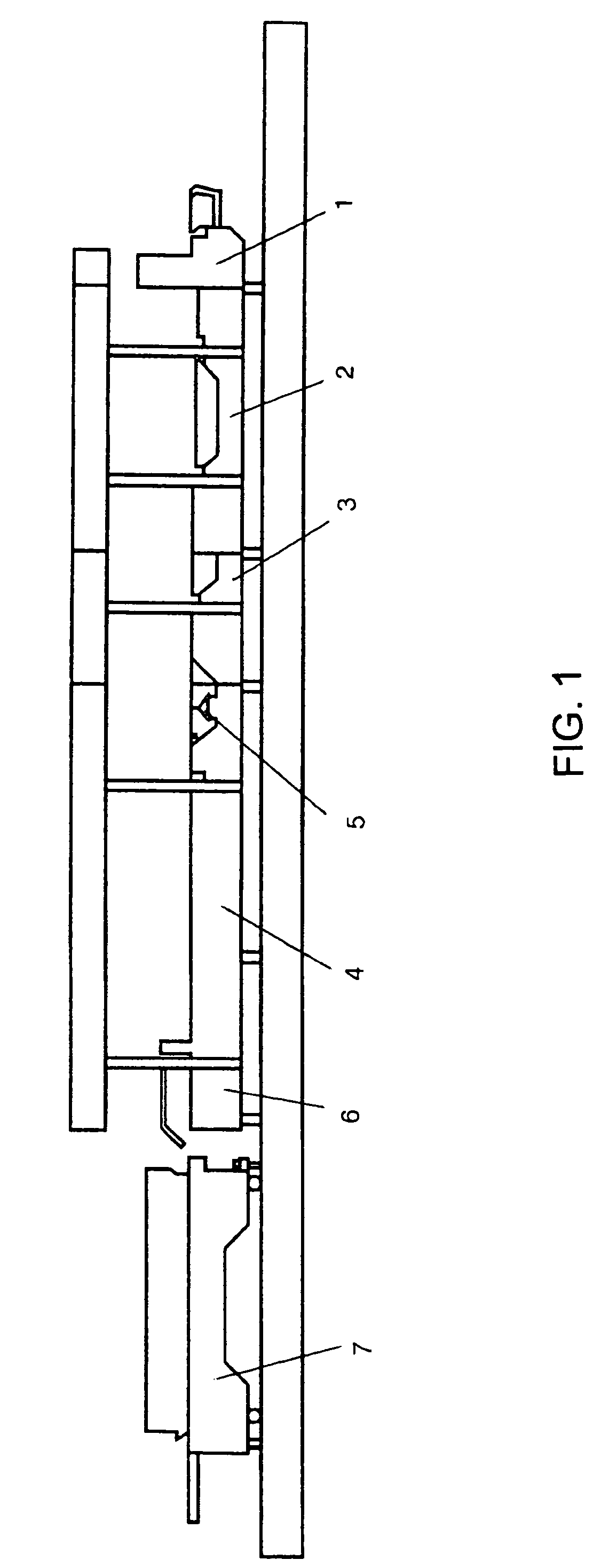
[0021]Referring now to the figures of the drawing in detail and first, particularly, to FIG. 1 thereof, there is shown in a conveying direction (from right to left), a folded box machine beginning with a feeder 1, which pulls the blanks to be processed out of a stack one after another at high speed and feeds them individually to the following processing station. The feeder 1 is followed, as next processing stations, by two pre-creasers 2, 3, which contain folding elements in order to fold folding flaps forward and back. As a result of being bent through 180°, the corresponding left-hand grooved lines of the blanks are made soft and supple.

[0022]The pre-creaser 3 is followed, as the next processing station, by the folding station 4, at the start of which an applicator 5 for adhesive, normally glue, is disposed. The adhesive applicator 5 contains glue nozzles or glue disks, by which the adhesive is applied to the blanks in the form of strips. The folding flaps of the blanks are then f...


PUM


Abstract

A gathering and pressing device for a folded box gluing machine has two machine-width, circulating conveyor belts which are connected to a drive and whose conveying runs are disposed horizontally, one above the other and running parallel to each another. An upper conveying run of the lower conveyor belt being mounted such it can be moved vertically with respect to the lower conveying run of the upper conveyor belt in order to press the folded blanks. Both the lower conveyor belt and the upper conveyor belt having their own drive which includes a servomotor with a resolver connected directly to the respective drive roll.

Description

BACKGROUND OF THE INVENTIONField of the Invention[0001]The invention relates to a gathering and pressing device for a folded box gluing machine. The device has two machine-width, circulating conveyor belts, which are connected to a drive and whose conveying runs are disposed horizontally, one above the other and running parallel to each another. The upper conveying run of the lower conveyor belt is mounted such that it can be moved vertically with respect to the lower conveying run of the upper conveyor belt in order to press the folded blanks.[0002]As is known, a folded box gluing machine for producing folding boxes from blanks have at least the now described processing stations. A feeder, which pulls the blanks to be processed from a stack one after another at high speed and feeds them individually to the following processing station. A folding station, in which the blank parts provided with a strip of glue are folded in order to produce a glued joint. A transfer station, from whi...

Claims


Application Information

Patent Timeline
Patent Type & Authority Patents(United States)
IPC IPC(8): B31B3/00B31B1/00B31B1/02B31B5/36B31B50/02B31B50/56B31B50/62B31B50/88B31B50/94B31B50/96B65G15/14B65G43/00B65H29/12
CPCB31B1/62B31B1/96B31B2201/6021B31B2201/925B31B2203/003B31B2203/082B31B50/00B31B50/96B31B2100/00B31B2120/30B31B50/626B31B2100/0022
Inventor SARO, KARLDIEHR, WOLFGANGNABER, KLAUSTORKA, KLAUS
Owner MASTERWORK GROUP CO LTD
Why Eureka
Try Eureka