
Bipolar battery and a method for manufacturing a bipolar battery

a bipolar battery and manufacturing method technology, applied in the field of bipolar batteries, can solve the problems of difficult to achieve, disadvantage of the described battery, and creation of an electrolyte path between adjacent cells, and achieve the effect of simplifying construction

Active Publication Date: 2007-08-21
NILAR INT AB
View PDF10 Cites 16 Cited by
  • Summary
  • Abstract
  • Description
  • Claims
  • Application Information

AI Technical Summary

Benefits of technology

The design achieves reduced manufacturing costs, improved seal reliability, and enhanced performance by ensuring uniform current and voltage distribution, rapid gas recombination, and efficient heat dissipation, addressing the issues of electrolyte paths and pressure differences.

Problems solved by technology

A problem that has occurred is the creation of an electrolyte path between adjacent cells due to inadequate sealing properties, which in turn mainly depend on a pressure difference between adjacent cells.
Although the problem with pressure differences between the cells is solved, there is still a disadvantage with the described battery.
The outer sealing around the edge of each biplate still has to be fluid-tight, which is very difficult to achieve.
Furthermore, the suggested solution is rather expensive to implement since an opening has to be made through the biplate to create the common pressure chamber.
If the biplate is relatively thin, it is even harder to create an opening through the biplate because tears, stretching, or metal slivers may form.

Method used


Image

  • Bipolar battery and a method for manufacturing a bipolar battery
  • Bipolar battery and a method for manufacturing a bipolar battery
  • Bipolar battery and a method for manufacturing a bipolar battery

Examples


first embodiment

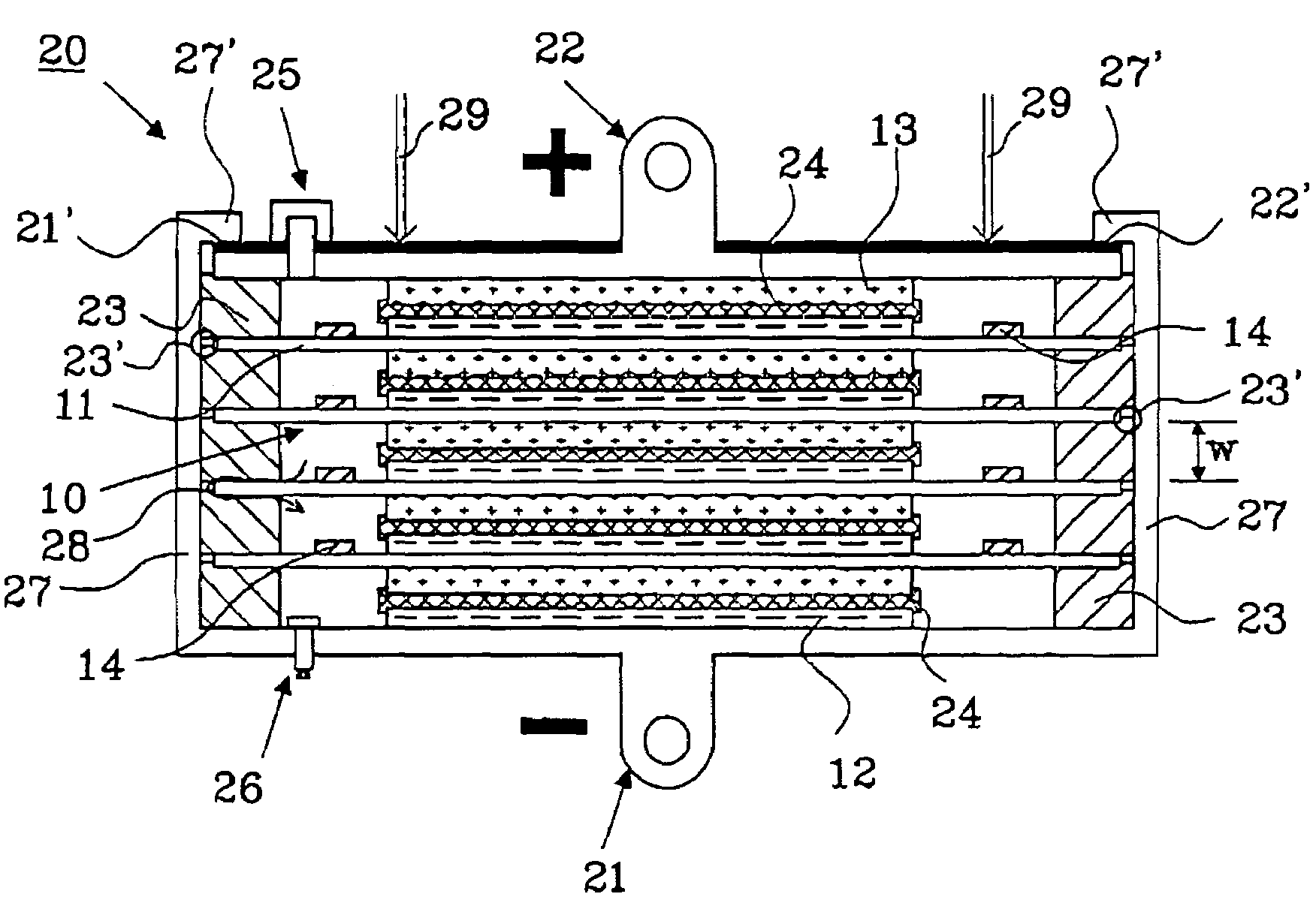
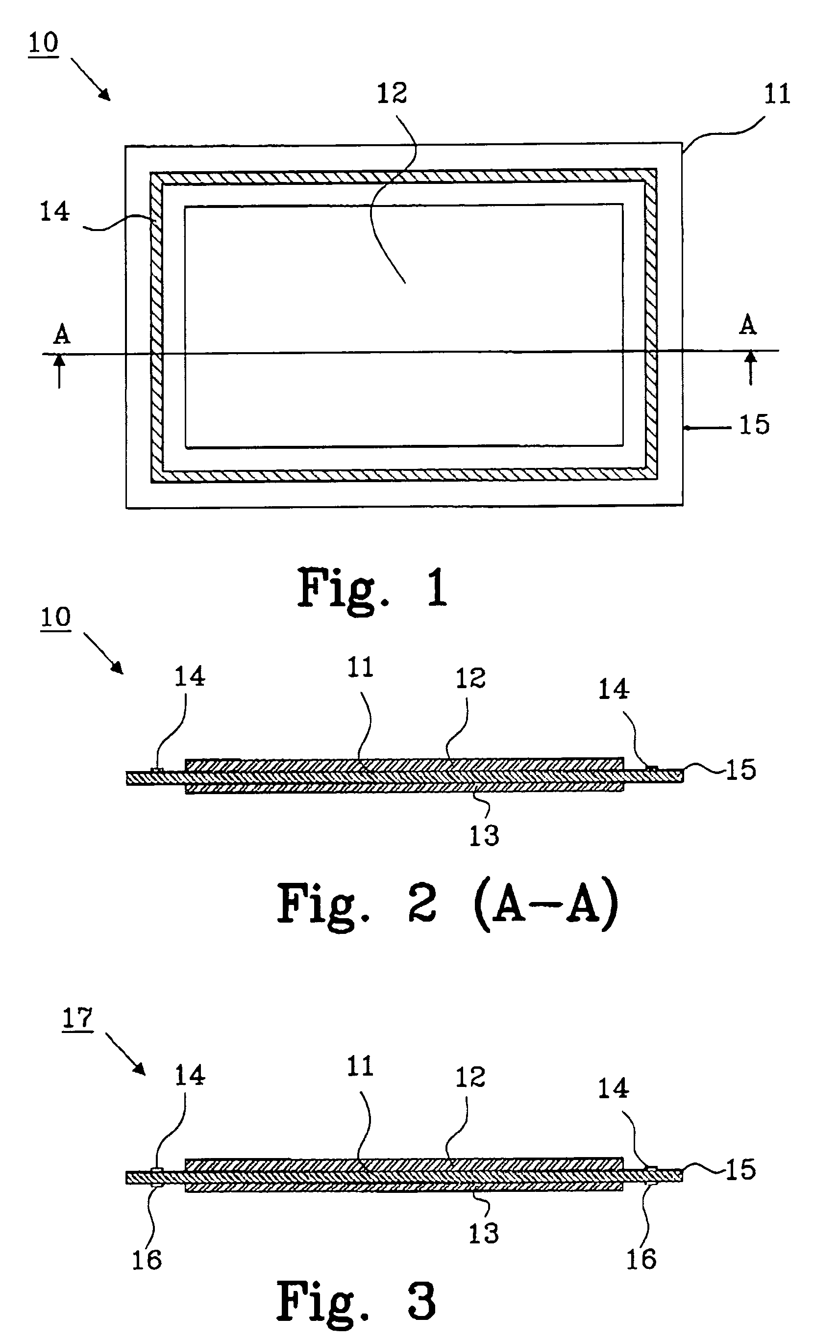
[0040]FIG. 1 is a planar view and FIG. 2 is a cross sectional view (along A-A in FIG. 1) of a biplate assembly 10 comprising a biplate 11, preferably made from Nickel or Nickel plated steel. A negative electrode 12 and a positive electrode 13 are attached to opposite sides, respectively, of the biplate 11. Each electrode is, in this embodiment, arranged to cover only a central portion of the side of the biplate 11 to leave space between each electrode and the edge 15 of the biplate 11 for implementing a means for creating a common gas space for all cells in the battery as described in connection with FIGS. 4 and 5. A hydrophobic electrolyte barrier 14, preventing electrolyte leakage, is provided on one side of the biplate 11 around the electrode, preferably the negative electrode 12, as illustrated in the embodiment.

[0041]The essential part of the invention is that the electrolyte leakage around the perimeter of the electrodes is controlled by the hydrophobic barrier. It is not even...

second embodiment

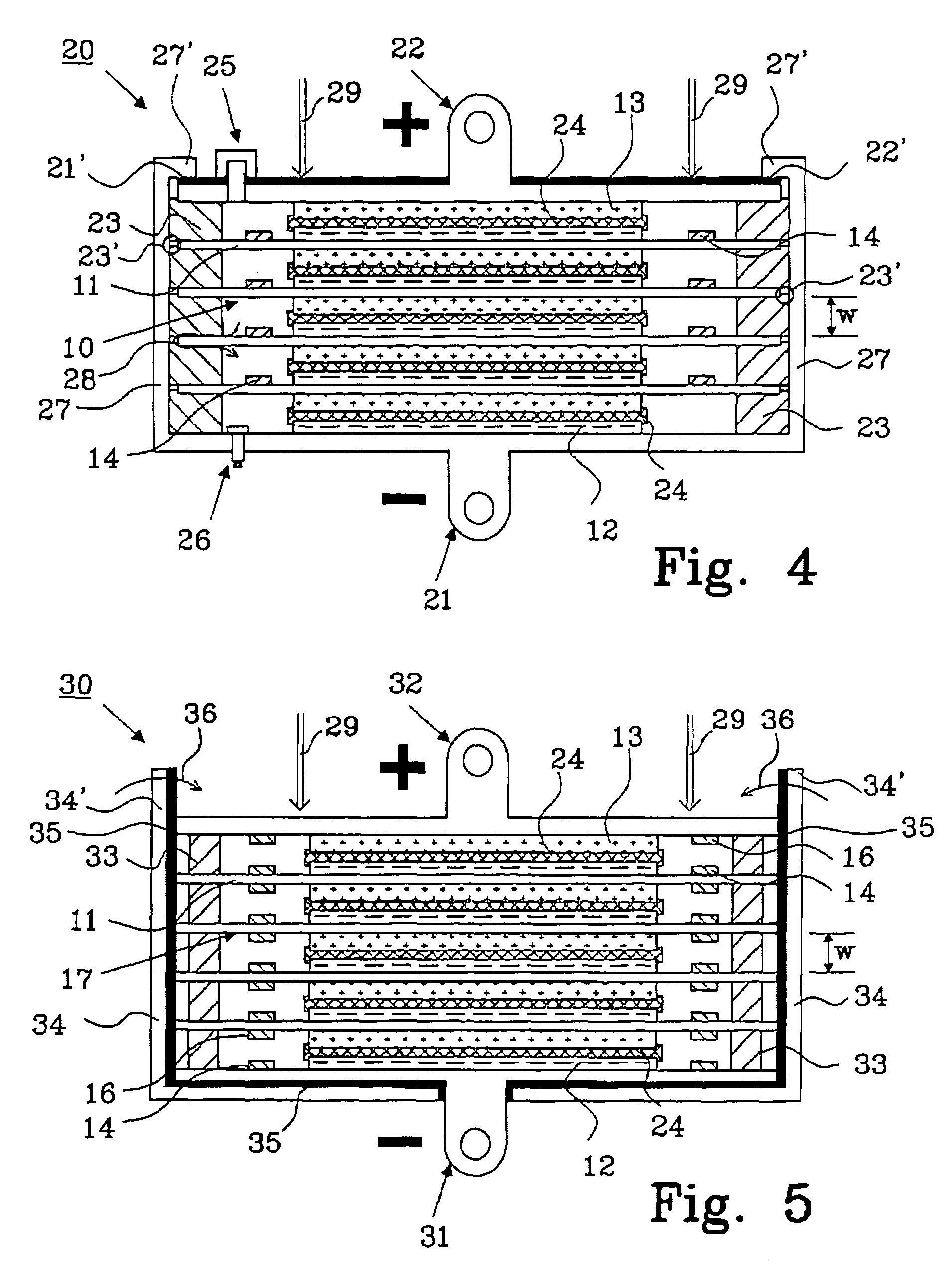
[0063]FIG. 5 shows a bipolar battery 30 according to the invention, comprising a negative end terminal 31, a positive end terminal 32 and four stacked biplate assemblies 17. The construction of this battery differs from the battery described in connection with FIG. 4 in the following way.

[0064]No recess is present in the frame 33 determining the width w of each cell. Hydrophobic electrolyte barriers 14 and 16 are present around both the negative electrode 12 and the positive electrode 13 that will prevent passages of electrolyte from one cell to another around the edge of the biplate 11. is Hydrophobic barriers are even present around the negative 12 and positive 13 electrodes of the end terminals, although this is not necessary to maintain operation of the battery. A metallic casing 34 is provided having an insulating layer 35 arranged on the inside, and a separate negative end terminal 31 is therefore present.

[0065]The main feature of the second embodiment is that it is possible t...

third embodiment

[0080]FIG. 6 shows a planar view of a biplate assembly 40, and FIG. 7 shows a cross-sectional view along A-A in FIG. 6. A negative electrode 12 and a positive electrode 13 are arranged on each respective side of a biplate 11, as previously described in connection with FIGS. 1-3.

[0081]A hydrophobic barrier 41 is provided around the edge of the biplate 11. In this embodiment, a part of the positive and negative side of the biplate 11 is covered with the hydrophobic barrier, although this is not necessary to obtain the advantages of the hydrophobic barrier. However, the biplate will in some applications be very thin and there will be a problem when attaching the hydrophobic barrier only to the edge of the biplate 11.

[0082]FIG. 8 shows a third embodiment of a bipolar battery 50 using biplate assemblies 40 as disclosed in FIG. 6 and 7. The basic construction of the battery 50 is the same as the battery described in connection with FIG. 4 with a few exceptions:[0083]Frames 51 of a differe...


PUM

PropertyMeasurementUnit
diameteraaaaaaaaaa
thicknessaaaaaaaaaa
widthaaaaaaaaaa

Abstract

The present invention relates to a bipolar battery, especially a NiMH battery, having: a sealed housing, a negative end terminal, a positive end terminal, and at least one biplate assembly comprising a biplate, a positive and a negative electrode. A separator is arranged between each negative and positive electrode forming a battery cell, said separator includes an electrolyte. An inner barrier of a hydrophobic material is arranged around at least one electrode, whereby said inner barrier prevents an electrolyte path from one cell to another cell, and a frame is present to provide predetermined cell spacing between each biplate and / or biplate and end terminal. The frame is attached in such a way to each biplate to permit ambient gas to pass between adjacent cells, thereby creating a common gas space for all cells in the battery. The invention also relates to a method for manufacturing a bipolar battery.

Description

TECHNICAL FIELD[0001]The present invention relates to a bipolar battery, especially a NiMH battery. The invention also relates to a method for manufacturing a bipolar battery.BACKGROUND TO THE INVENTION[0002]Traditionally, bipolar batteries including several cells have been designed to have separately sealed cells to contain both electrolyte and gas created during operation. A problem that has occurred is the creation of an electrolyte path between adjacent cells due to inadequate sealing properties, which in turn mainly depend on a pressure difference between adjacent cells. The pressure difference arises when a cell starts to gas before the cell next to it starts gassing. This is a normal behaviour of cells in a bipolar battery.[0003]A solution to this problem has been suggested in U.S. Pat. No. 5,344,723 by Bronoel et al., which discloses a bipolar battery having a common gas chamber, which is created by providing an opening through the biplate (conductive support / separator). The...

Claims


Application Information

Patent Timeline
Patent Type & Authority Patents(United States)
IPC IPC(8): H01M6/48H01M10/18H01M10/52H01MH01M2/12H01M2/18H01M4/02H01M4/24H01M4/80H01M10/04H01M10/28H01M10/34
CPCH01M2/12H01M4/24H01M4/80H01M10/0418H01M10/044H01M10/287H01M10/347H01M10/282Y10T29/4911H01M2004/029Y02E60/124H01M10/345Y02E60/10H01M50/325H01M50/30Y02P70/50
Inventor FREDERIKSSON, LARSPUESTER, NEIL H.
Owner NILAR INT AB
Learn More