Compact coaxial nozzle for laser cladding

a coaxial nozzle and laser cladding technology, applied in welding equipment, metal-working equipment, manufacturing tools, etc., can solve the problems of insufficient repair strategies of gas turbine engine components, high cost of components, and difficulty in achieving so as to improve the quality of inert gas blanketing

Inactive Publication Date: 2007-08-21
HONEYWELL INT INC
View PDF18 Cites 59 Cited by
  • Summary
  • Abstract
  • Description
  • Claims
  • Application Information

AI Technical Summary

Benefits of technology

[0012]The present invention provides a compact coaxial nozzle that is useful in performing laser welding repairs such as laser cladding. The nozzle has a conical, streamlined contour such that it may be used on components with complex curvature and confined geometry, such as for example, turbine engine blisks and impellers. Further the nozzle distributes shielding gas through a ring passage, thus improving on the quality of inert gas blanketing achieved by other distributor plate arrangements. Finally, the nozzle may be used with known laser welding equipment.

Problems solved by technology

These components are frequently expensive such that their repair, rather than replacement, is economically justified.
Further the components are often made of high strength, high performance alloys such that other welding repair techniques will not service these materials, unless they are combined with other methods such as a pre-weld heat treatment.
Recently it has been found that conventional laser welding equipment will not adequately repair certain kinds of gas turbine engine components.
The development of the blisk as a gas turbine engine component has presented challenges with respect to repair strategies.
Individual airfoils are now permanently attached to the rotor disk, which means that damaged airfoils cannot easily be removed for repair, as has been done with individual turbine blades.
Blade leading edge damage, for example, is a common failure experienced in blisks.
The leading edge is subject to foreign object damage or erosion after a period of service time.
The option of throwing out worn engine components such as blisks and replacing them with new ones is not an attractive alternative.
Blisks are very expensive due to costly material and manufacturing processes.
Disadvantageously, the superalloys generally are very difficult to weld successfully.
Traditional repair methods have proven less than satisfactory for superalloy materials.
However, at such an elevated temperature the airfoil may experience heat cracking and fracturing, rendering the blade unusable for further engine service.
Other welding techniques similarly suffer from a lack of thermal control and provide too much localized heat during welding to render an effective repair.
Superalloys are susceptible to microcracking during localized heating.
In addition to the welding challenges presented by the component material, the geometrical configuration of blisks, impellers, and similar devices also makes conventional welding very difficult.
The complex geometry of the airfoil, and particularly, the shape of the leading edge, makes it difficult to deposit filler or cladding material thereon.
However, in doing so, the nozzle or other welding apparatus may impact neighboring airfoils.
The confined geometry of the airfoil thus makes it difficult to apply a laser beam to points other than the extreme outer surfaces of a blisk using conventional equipment.
Thus, laser welding performed with known designs of laser nozzles has shown the drawbacks of the prior art.
In one aspect laser nozzles are bulky.
However, these pieces of the prior art nozzles often interfere with positioning and movement of the nozzle.
However, the position of these holes can cause turbulence in the flow patterns of the shielding gas.
Turbulence can degrade the quality of the inert gas shielding.

Method used


Image

  • Compact coaxial nozzle for laser cladding
  • Compact coaxial nozzle for laser cladding
  • Compact coaxial nozzle for laser cladding

Examples


Embodiment Construction

[0024]The following detailed description of the invention is merely exemplary in nature and is not intended to limit the invention or the application and uses of the invention. Furthermore, there is no intention to be bound by any theory presented in the preceding background of the invention or the following detailed description of the invention. Reference will now be made in detail to exemplary embodiments of the invention, examples of which are illustrated in the accompanying drawings. Wherever possible, the same reference numbers will be used throughout the drawings to refer to the same or like parts.

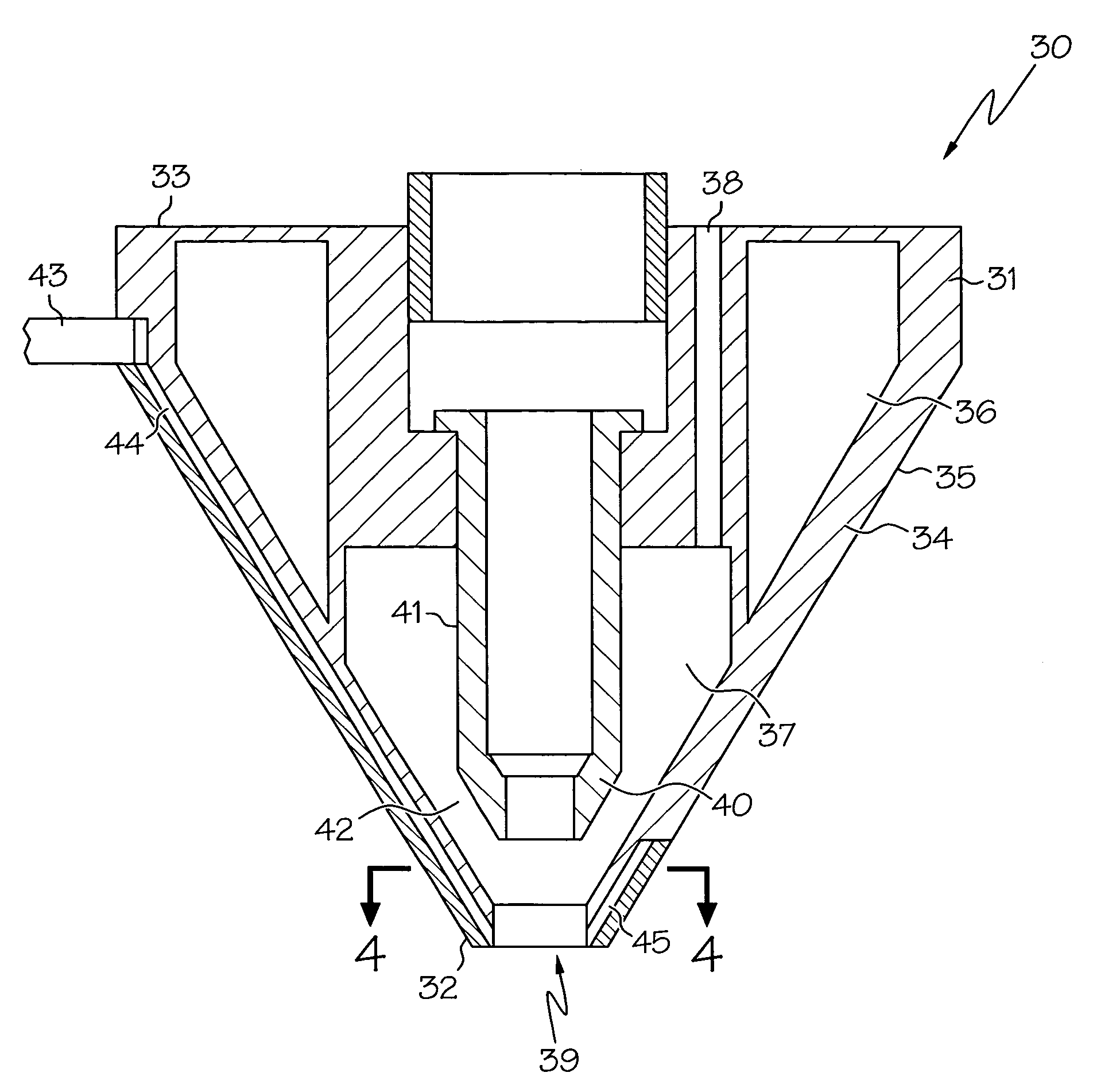
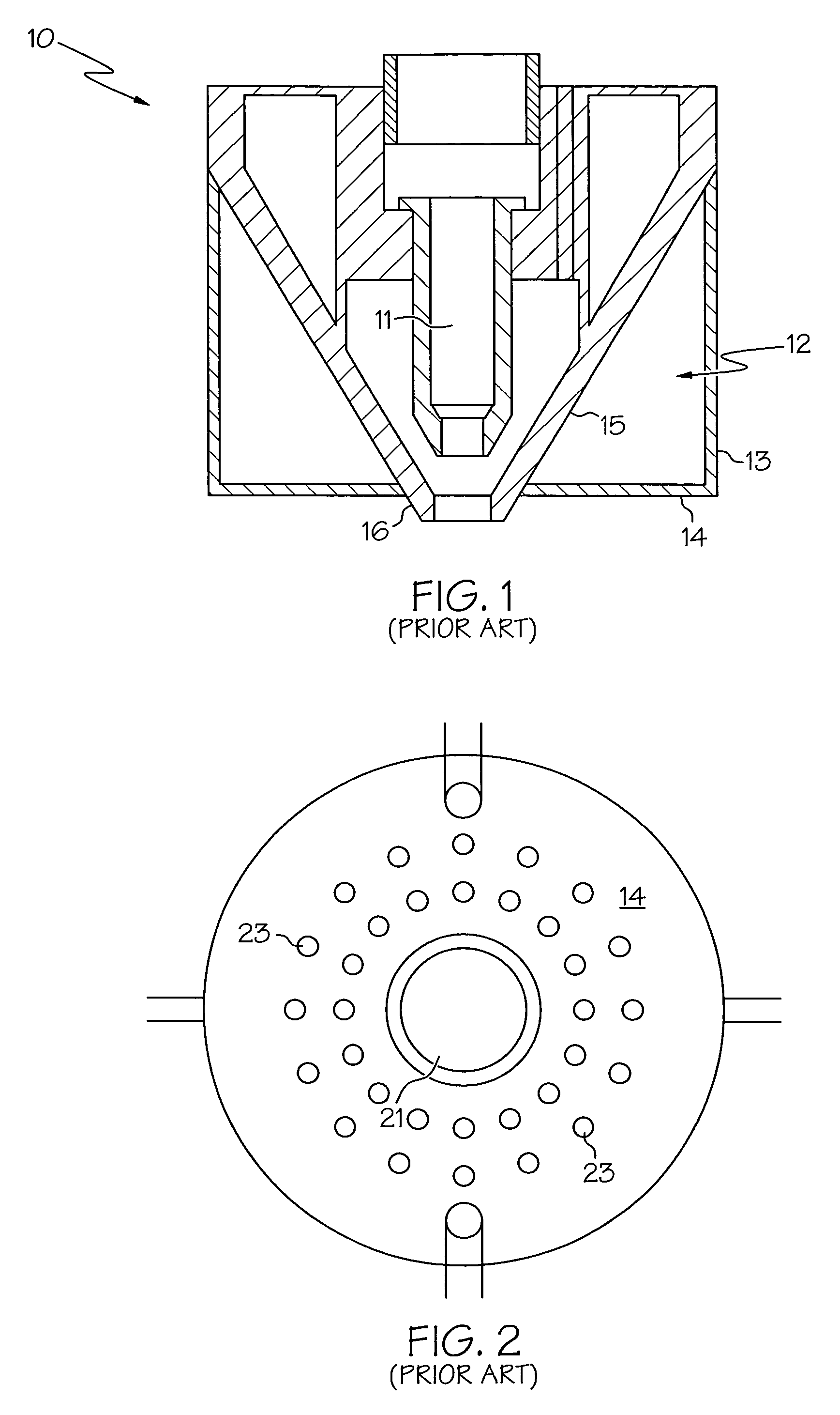
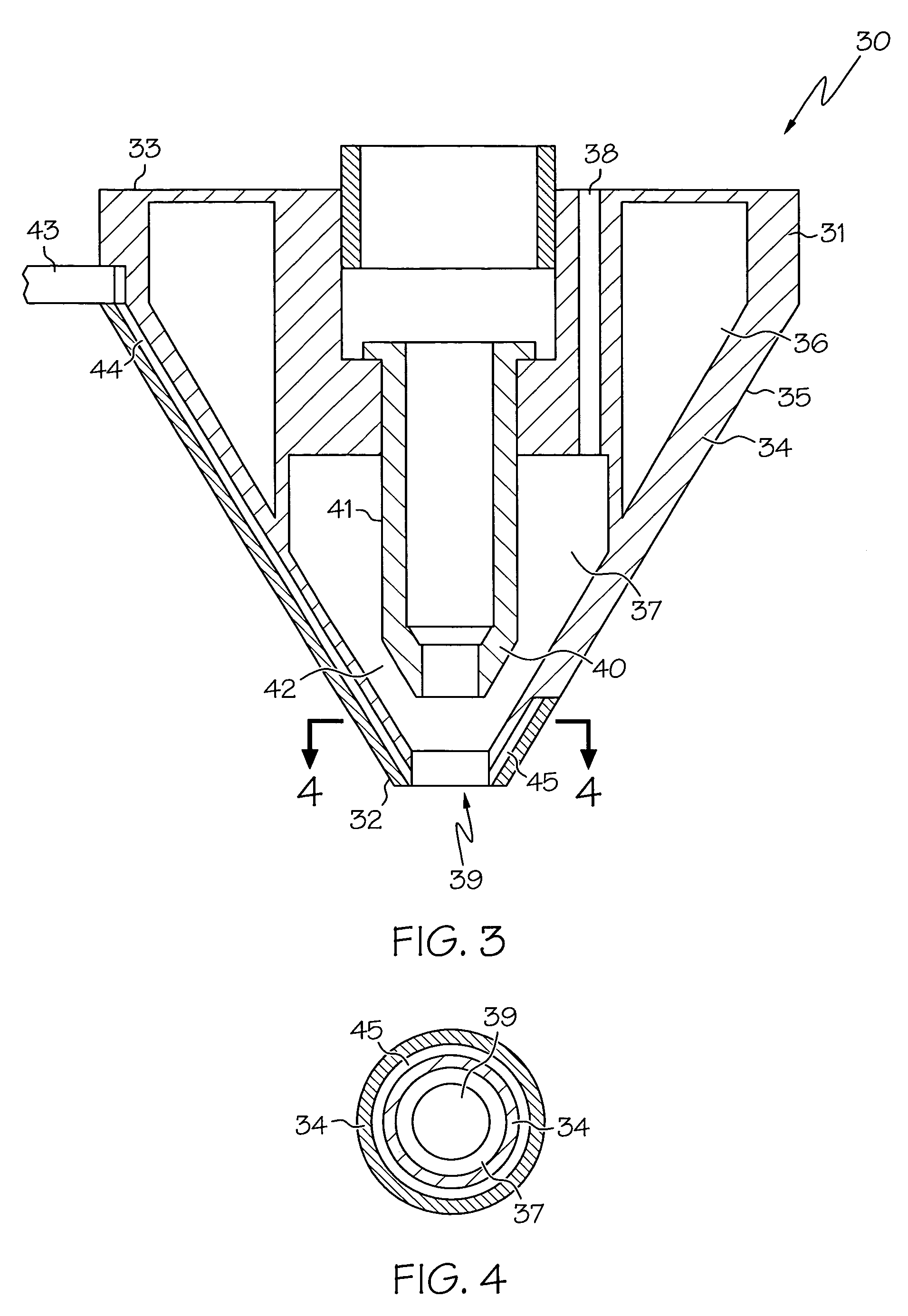
[0025]Referring now to FIG. 1 there is shown a representation of a prior art nozzle. The nozzle 10 includes a central chamber 11 through which is projected the laser. Chamber 11 includes laser transmission means such as fiber optic cables or laser-carrying channels and beam guides. Central chamber 11 extends until it terminates at tip 16 which is the point where a laser exits nozzle ...


PUM

PropertyMeasurementUnit
angleaaaaaaaaaa
temperaturesaaaaaaaaaa
angleaaaaaaaaaa

Abstract

The present invention provides a compact coaxial nozzle useful in laser welding operations where the welding piece has a restricted or confined geometry. The nozzle is generally conical in shape, terminating in a relatively small tip. The nozzle includes a central laser discharge opening. The conical shape allows movement of the nozzle in confined areas. The nozzle includes a cooling jacket for proving coolant to the nozzle. The nozzle also includes a powder mixing chamber that provides good mixing of powdered filler material with a coaxial discharge around the laser. Finally, the nozzle further provides for inert gas to pass from an upper inlet, through passageways, out of a ring discharge. The ring discharge is also coaxially disposed around the central laser. Further the ring discharge provides mixing of the inert gas in order to minimize turbulent flow problems associated with restrictor plates.

Description

FIELD OF THE INVENTION[0001]The present invention relates to laser cladding with powdered filler. More particularly, the invention relates to a compact coaxial nozzle that may be used in welding applications where the confined geometry of the weldpiece requires a small nozzle to gain access to the welding surface.BACKGROUND OF THE INVENTION[0002]Welding techniques such as laser welding are being used more frequently as a means to repair and restore various types of worn components. Laser welding operations include procedures such as the welding or joining or parts and material deposition or cladding. Laser welding has found particular application in the repair of gas turbine engine components. These components are frequently expensive such that their repair, rather than replacement, is economically justified. Further the components are often made of high strength, high performance alloys such that other welding repair techniques will not service these materials, unless they are comb...

Claims


Application Information

Patent Timeline
Patent Type & Authority Patents(United States)
IPC IPC(8): B23K26/34B23K26/14
CPCB23K26/1411B23K26/1476B23K26/144
Inventor GUO, WEN
Owner HONEYWELL INT INC
Why Eureka
Try Eureka