Method and device for injecting a noise signal into a paired wire communication link

a communication link and noise signal technology, applied in the field of communication systems, can solve the problems of line uncoupling, the line that transmits voice signals might not work well for data signals, and the line that transmits voice signals works well for data signals. , to achieve the effect of low impedance, low impedance and low impedan

Inactive Publication Date: 2007-08-21
SPIRENT COMM
View PDF4 Cites 13 Cited by
  • Summary
  • Abstract
  • Description
  • Claims
  • Application Information

AI Technical Summary

Benefits of technology

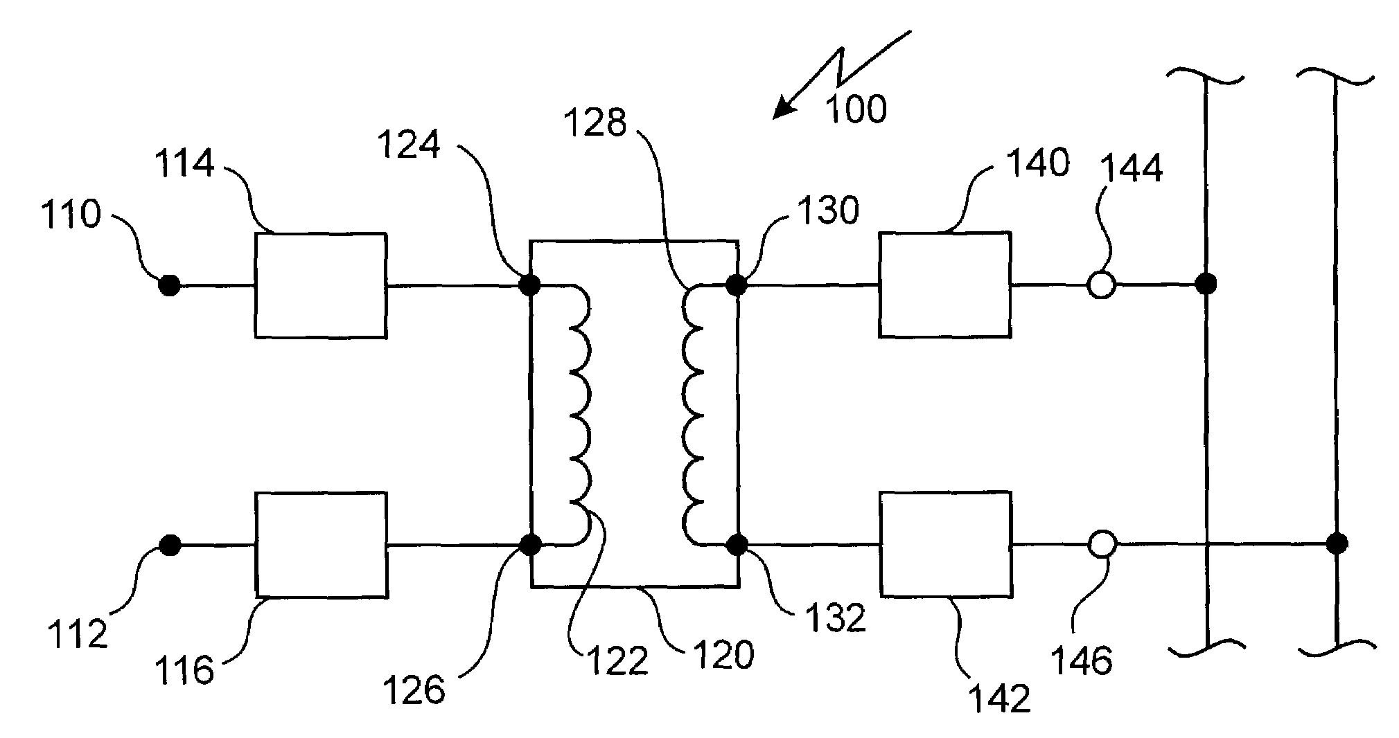
[0008]In accordance with the present invention there is provided a device for injecting a noise signal into a first wire and a second wire of a communication link comprising: a first input port; a second input port for, in combination with the first input port, receiving a differential mode noise signal for being injected into the communication link; a first transformer having a primary coil and a secondary coil, the primary coil and the secondary coil, each having a first end tap and a second end tap, the first end tap and the second end tap of the primary coil coupled to the first input port and the second input port, respectively; a first output port in electrical communication with the first end tap of the secondary coil, the first output port for being connected to the first wire, for injecting a first portion of the differential mode noise signal into the communication link; a second output port in electrical communication with the second end tap of the secondary coil, the second output port for being connected to the second wire, for injecting at least a second portion of the differential mode noise signal into the communication link; a first resistor interposed between the first input port and the first end tap of the primary coil; and, a second resistor interposed between the second input port and the second end tap of the primary coil, the first resistor and the second resistor providing a high impedance at the first output port and the second output port.
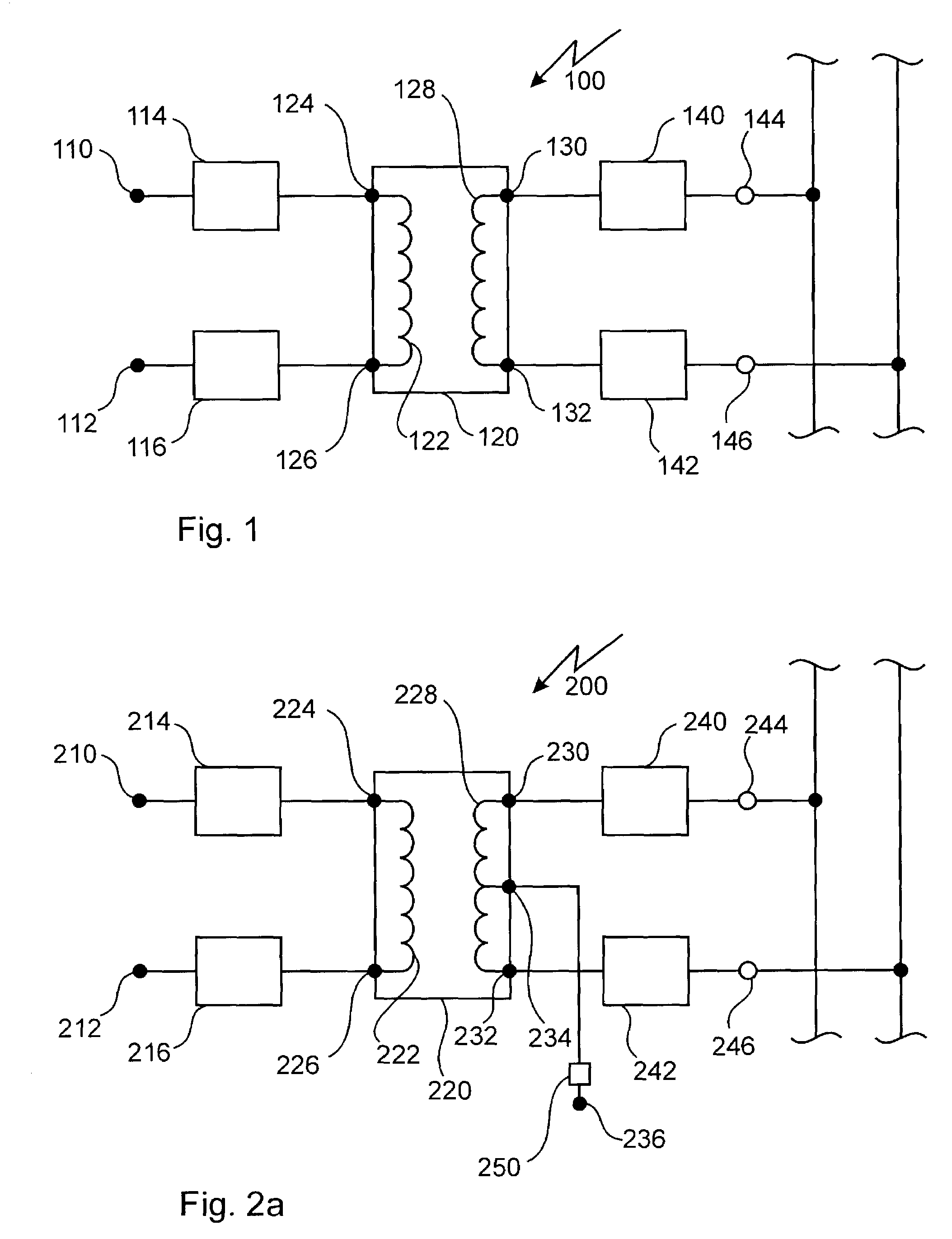
[0009]In accordance with an aspect of the present invention there is provided a device for injecting a noise signal into a first wire and a second wire of a communication link comprising: a third input port for receiving a common mode noise signal for being injected into the communication link; a first transformer having a primary coil and a secondary coil, the primary coil having a first end tap, a center tap and a second end tap, the secondary coil, having a first end tap and a second end tap, the center tap of the primary coil coupled to the third input port; a first output port in electrical communication with the first end tap of the secondary coil, the first output port for being connected to the first wire, for injecting the common mode noise signal into the communication link; a second output port in electrical communication with the second end tap of the secondary coil, the second output port for being connected to the second wire, for injecting the common mode noise signal into the communication link; a third resistor disposed between the secondary coil and the first output port, the third resistor having low impedance; and, a fourth resistor, disposed between the secondary coil and the second output port, the fourth resistor having low impedance.
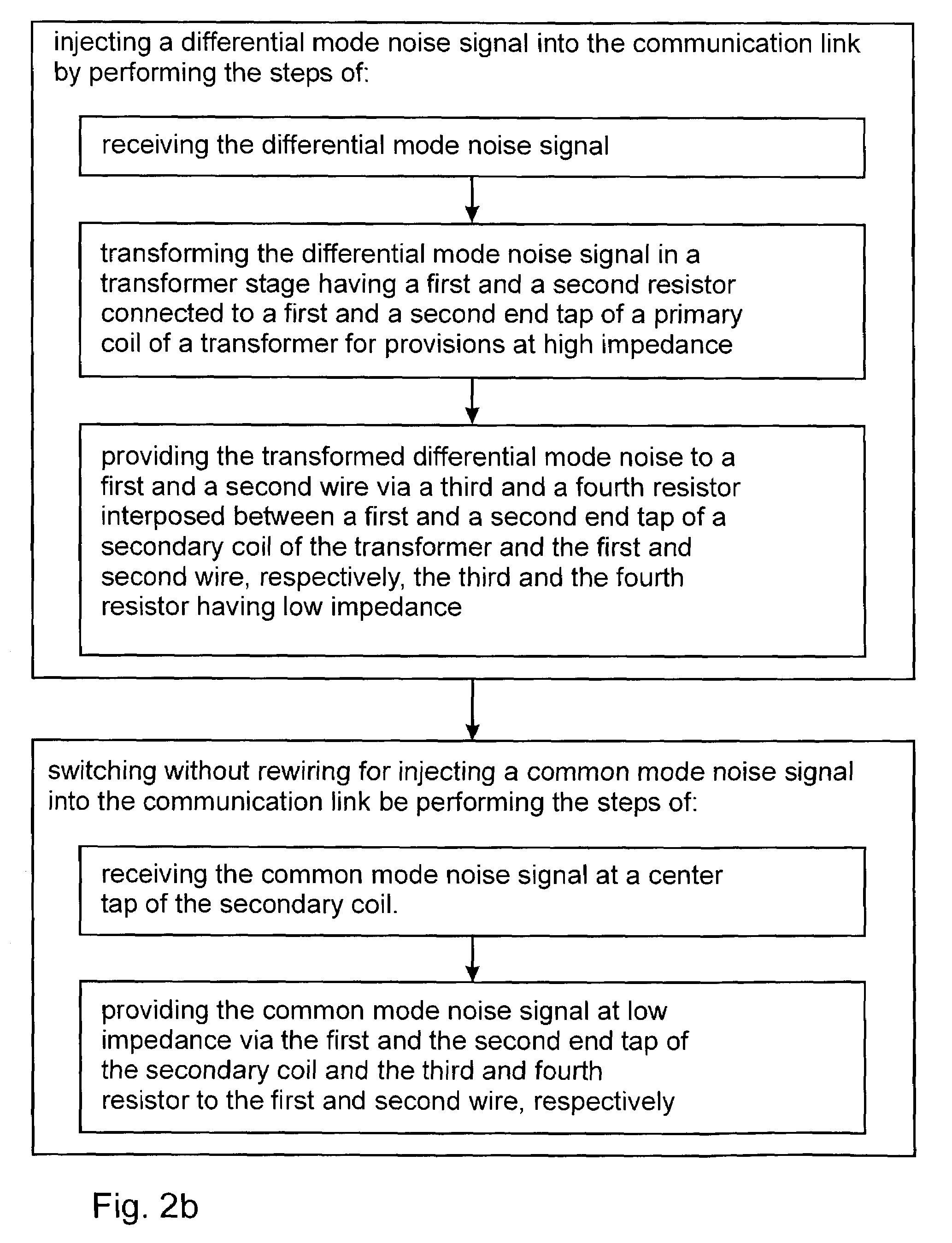
[0010]In accordance with an aspect of the present invention there is also provided a method for injecting a noise signal into a pair of wires of a communication link comprising the steps of: injecting a differential mode noise signal into the communication link by performing the steps of: receiving the differential mode noise signal; transforming the differential mode noise signal in a transformer stage having a first and a second resistor connected to a first and a second end tap of a primary coil of a transformer for provision at high impedance; and, providing the transformed differential mode noise signal to a first and a second wire via a third and a fourth resistor interposed between a first and a second end tap of a secondary coil of the transformer and the first and the second wire, respectively, the third and the fourth resistor having low impedance; and, switching without rewiring for injecting a common mode noise signal into the communication link by performing the steps of: receiving the common mode noise signal at a center tap of the secondary coil; and, providing the common mode noise signal at low impedance via the first and the second end tap of the secondary coil and the third and the fourth resistor to the first and the second wire, respectively.
[0011]In accordance with an aspect of the present invention there is also provided a communication device tested by the steps of: injecting a noise signal into a signal propagating within a line coupled with the communication device with a noise injection circuit comprising: a first input port; a second input port for, in combination with the first input port, receiving a differential mode noise signal for being injected into the communication link; a first transformer having a primary coil and a secondary coil, the primary coil and the secondary coil, each having a first end tap and a second end tap, the first end tap and the second end tap of the primary coil coupled to the first input port and the second input port, respectively; a first output port in electrical communication with the first end tap of the secondary coil, the first output port for being connected to the first wire, for injecting a first portion of the differential mode noise signal into the communication link; a second output port in electrical communication with the second end tap of the secondary coil, the second output port for being connected to the second wire, for injecting at least a second portion of the differential mode noise signal into the communication link; a first resistor interposed between the first input port and the first end tap of the primary coil; and, a second resistor interposed between the second input port and the second end tap of the primary coil, the first resistor and the second resistor providing a high impedance at the first output port and the second output port; and, testing the device performance in the presence of the injected noise.

Problems solved by technology

However, to achieve such high data rates, DSL services operate at higher frequencies and are thus more sensitive to the length and quality of the copper loop.
As a result, a POTS line that works well transmitting voice signals might not work well for data signals.
However, in both prior art systems the line needs to be uncoupled at one end or split for injecting of the noise signal.

Method used


Image

  • Method and device for injecting a noise signal into a paired wire communication link
  • Method and device for injecting a noise signal into a paired wire communication link
  • Method and device for injecting a noise signal into a paired wire communication link

Examples


Embodiment Construction

[0017]Referring to FIG. 1 a simple embodiment of a device 100 for injecting a noise signal into a pair of wires of a communication link according to the invention is shown. In operation a differential mode noise signal is received at input ports 110 and 112, which are connected via resistors 114 and 116 to end taps 124 and 126 of a primary coil 122 of transformer 120, respectively. The transformed differential mode noise signal is then transmitted via end taps 130 and 132 of a secondary coil 128 of the transformer 120 and resistors 140 and 142 to output ports 144 and 146 for injection into a first and a second wire of the communication link. In order to not disturb the impedance of a communication link under test the differential mode noise signal is injected at high impedance. This is achieved in the device 100 through the combination of the resistors 114 and 116 having relatively high impedance with a predetermined range with the transformer 120. By combining a resistor with a tra...


PUM


Abstract

The present invention relates to a device and method for injecting a noise signal into a wire pair of a communication link. In operation a differential mode noise signal is received at a first and a second input port, which are connected via a first and a second resistor to a first and a second end tap of a primary coil of a transformer, respectively. The transformed differential mode noise signal is then transmitted via a first and a second end tap of a secondary coil of the transformer and a third and a fourth resistor to a first and a second output port for injection at high impedance into a first and a second wire of the communication link. Optionally, the device comprises a third input port connected to a center tap of the secondary coil for receiving a common mode noise signal. The common mode noise signal is then provided at low impedance to the first and the second wire via the first and the second end tap of the secondary coil and via the third and fourth resistor having low impedance, respectively. The device allows injection of a noise signal into the communication link at a desired location without splitting the same. Furthermore, the device allows injection of differential mode noise signals and common mode noise signals using same circuitry without switching and/or rewiring between different electrical circuits.

Description

[0001]This application claims benefit from U.S. Provisional Application No. 60 / 401,346 filed Aug. 7, 2002.FIELD OF THE INVENTION[0002]This invention relates to communication systems and in particular to a method and a device for injecting a noise signal into a paired wire communication link for testing.BACKGROUND OF THE INVENTION[0003]Recently, there have been dramatic changes in the telecommunications industry. For example, deregulation of local markets resulted in the emergence of new technologies in this industry. Furthermore, a growing demand for Internet access sparked development of new technologies that deliver high speed data services using existing infrastructure.[0004]As is well known in the industry, Digital Subscriber Line, or DSL, is one of the most promising new technologies for delivering superior service and high speed connections using the existing infrastructure. DSL service is implemented in several different ways, such as asymmetrical DSL, or ADSL, where upstream...

Claims


Application Information

Patent Timeline
Patent Type & Authority Patents(United States)
IPC IPC(8): H04B3/00H04B3/46H04L1/24H04L27/26
CPCH04B3/46H04L1/24H04L27/2601
Inventor GOLO, DRAGAN
Owner SPIRENT COMM
Why Eureka
Try Eureka