Wind noise suppression in directional microphones

a directional microphone and wind noise technology, applied in the field of directional microphones, can solve the problems of poor signal-to-noise ratio of directional microphones at low frequencies, increased velocity of air, and increased noise of directional microphones, so as to reduce the likelihood of low frequency masking, less of a tendency for microphone overload, and the effect of wind noise suppression

Inactive Publication Date: 2007-08-21
SONION NEDERLAND
View PDF7 Cites 6 Cited by
  • Summary
  • Abstract
  • Description
  • Claims
  • Application Information

AI Technical Summary

Benefits of technology

[0008]The wind noise suppression conduit presents an acoustical mass (i.e., related to acoustical inertance, and the acoustic equivalent of an electrical inductance) that, together with the acoustical resistances of the mechanical screens in the sound inlets, causes a low frequency roll-off of 6 dB / octave. When added to the inherent frequency roll-off of a directional microphone that is typically 6 dB / octave, the overall microphone has a low frequency roll-off at 12 dB / octave for its frequency response. Accordingly, wind noise is suppressed such that the wearer of the hearing aid receives a reduced output of wind noise that provides much less of a tendency for the microphone to overload and also much less of a likelihood for low frequency masking by the wind noise of the higher frequencies of the speech signal.

Problems solved by technology

Therefore, the signal-to-noise ratio of directional microphones is much poorer at low frequencies, which makes them more sensitive to low frequency noise sources, like wind noise.
For some obstacles, however, the velocity of the air increases and the air is diverted.
The amplitude difference, however, can be very large.
It is the pressure difference that causes the problem and results in a diaphragm displacement in the direction of the lowest pressure which, consequently, results in a relatively high microphone output.
The problem is accentuated for wind noise since the amplitude of the sound from the wind can be very high, which may deafen the desired sounds, such as those from speech.
These mechanical solutions do not, however, entirely solve the problem since the wind still produces an annoying sound to the wearer of the hearing aid.
Further, the use of an electronic high pass filter may not be effective in situations where high SPL noise sources cause overload in the input stage of the microphone amplifier.

Method used


Image

  • Wind noise suppression in directional microphones
  • Wind noise suppression in directional microphones
  • Wind noise suppression in directional microphones

Examples


Embodiment Construction

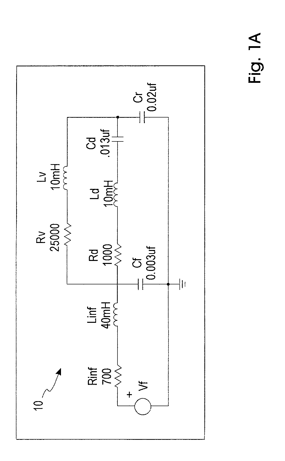
[0026]To appreciate the present invention, reference is made to the well-known analogy between acoustical networks and electrical circuits. In this analogy, acoustical compliance is analogous to electrical capacitance, acoustical inertance (or mass) is analogous to electrical inductance, and acoustical resistance is analogous to electrical resistance. Several of the acoustical networks will be described as electrical networks with values placed on the components of the networks. It should be understood that the application of the present invention is not limited to only those values listed, but can be applied to directional microphones having various values for the acoustical resistances, acoustical compliances, and acoustical inertances of the components in their acoustical networks.

[0027]FIG. 1A illustrates an electrical schematic that is analogous to the acoustical network 10 for a standard pressure microphone. Rinf and Linf are the acoustical resistance of the input screen place...


PUM


Abstract

A directional microphone includes a housing, a diaphragm dividing the housing into a front volume and a back volume, electronics for detecting signals corresponding to movements of the diaphragm, and front and back inlets for the front and back volumes, respectively. To obtain additional low frequency roll-off in the directional microphone, the directional microphone includes an elongated acoustical conduit connecting the front volume and the back volume. The acoustical conduit may be external or internal to the housing.

Description

RELATED APPLICATION[0001]This application claims the benefit of priority to U.S. Provisional Patent Application Ser. No. 60 / 261,493, filed Jan. 12, 2001.FIELD OF THE INVENTION[0002]The present invention relates to directional microphones and, specifically, to a directional microphone employing tubes or channels connecting the front and back volumes to reduce the undesirable effects of wind noise.BACKGROUND OF THE INVENTION[0003]Directional microphones have openings to both the front and back volumes and provide an output corresponding to the subtraction of two time delayed signals (i.e., the principle of directivity), resulting in a 6 dB / octave low frequency roll-off in their frequency response curves. Compared to pressure or omnidirectional microphones, the output for directional microphones is attenuated by the effective subtraction of the two input signals, while the noise is magnified by the presence of an essentially infinite rear or back volume. Therefore, the signal-to-noise ...

Claims


Application Information

Patent Timeline
Patent Type & Authority Patents(United States)
IPC IPC(8): H04R9/08H04R1/08H04R1/38H04R25/00
CPCH04R1/38H04R1/086H04R25/00H04R2410/07
Inventor DE ROO, DION IVOVAN HALTEREN, AARTBROEKHUIJSEN, BASTIAAN
Owner SONION NEDERLAND
Why Eureka
Try Eureka