Modeling a mixed-language mixed-signal design

a mixed-language mixed-signal and design technology, applied in the field of integrated circuit design and verification, can solve the problems of lack of compatibility between vhdl-ams and verilog-ams languages, lack of support for driver-receiver segregation (drs), and process of identification

Inactive Publication Date: 2007-08-21
CADENCE DESIGN SYST INC
View PDF4 Cites 9 Cited by
  • Summary
  • Abstract
  • Description
  • Claims
  • Application Information

AI Technical Summary

Benefits of technology

[0012]A method for modeling a mixed-language mixed-signal design environment containing VHDL-AMS and Verilog-AMS components is disclosed. The method provides seamless integration of VHDL-AMS and Verilog-AMS design components, and allows designers to use previously designed components from both Verilog-AMS and VHDL-AMS languages and to take advantages of the benefits from both languages.

Problems solved by technology

However, circuit designers are interested in working with design components from both languages, and do not want to be constrained to either the VHDL-AMS language or the Verilog-AMS language.
One of the problems in supporting a mixed-language mixed-signal design lies in the lack of compatibility between the VHDL-AMS and Verilog-AMS languages.
One such incompatibility is the lack of support for the driver-receiver segregation (DRS) methodology by the VHDL-AMS language.
One drawback of this approach is that the user has to know where such connections exist in a design.
However, the process of identifying these blocks and implementing the fixes or workarounds for such connections consumes a lot of time and effort.
However, this approach does not work if a given Verilog-AMS domainless net is connected to both a VHDL-AMS analog net and a VHDL-AMS digital net.
In addition to the limitations described above, other differences between Verilog-AMS and VHDL-AMS languages also impose challenges in implementing DRS in a mixed-language mixed-signal environment.
First, the VHDL-AMS language, being a strongly typed language, does not allow connections between analog and digital nets.
These differences add to the challenges of implementing DRS in an MLMS design.
The existing workarounds are inflexible and suffer a number of limitations.

Method used


Image

  • Modeling a mixed-language mixed-signal design
  • Modeling a mixed-language mixed-signal design
  • Modeling a mixed-language mixed-signal design

Examples


case 1

g-AMS Drivers with Verilog-AMS Receivers

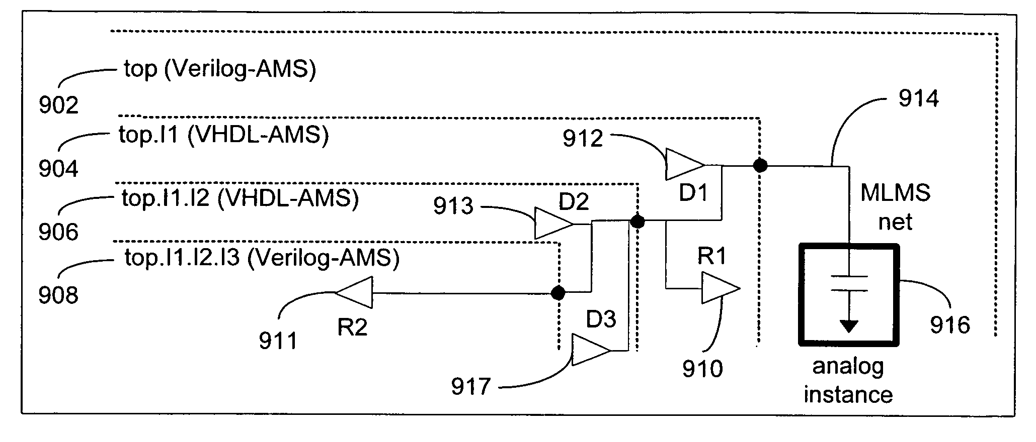
[0052]FIG. 4a illustrates a hierarchical design having one or more Verilog-AMS drivers and Verilog-AMS receivers in an MLMS environment. This scenario is distinguished from a pure Verilog-AMS design. In this case, an MLMS net can pass through VHDL-AMS blocks that do not receive or drive any values on the MLMS net. The hierarchical design may include hierarchical levels from both Verilog-AMS and VHDL-AMS languages. In particular, the hierarchical design includes a top level (Verilog-AMS) 402, a first sub-level top.I1 (VHDL-AMS) 404, a second sub-level top.I1.I2 (VHDL-AMS), and a third sub-level top.I1.I2.I3 (Verilog-AMS). The top level 402 includes a first Verilog-AMS receiver (R1) 410 and the third sub-level top.I1.I2.I3408 includes a first Verilog-AMS driver (D1) 412. D1 drives R1 through an MLMS net 414, which crosses both the Verilog-AMS and VHDL-AMS language boundaries. An analog instance 416 is attached to the MLMS net at the top level 40...

case 2

g-AMS Drivers with VHDL-AMS Receivers

[0055]FIG. 5a illustrates a hierarchical design having one or more Verilog-AMS drivers and VHDL-AMS receivers in an MLMS environment. The hierarchical design includes hierarchical levels from both Verilog-AMS and VHDL-AMS languages. In particular, the hierarchical design includes a top level (Verilog-AMS) 502, a first sub-level top.I1 (VHDL-AMS) 504, a second sub-level top.I1.I2 (VHDL-AMS) 506, and a third sub-level top.I1.I2.I3 (Verilog-AMS) 508. The top level 502 includes a first Verilog-AMS driver (D1) 510, the second sub-level top.I1 includes a first VHDL-AMS receiver (R1) 512, and the third sub-level top.I1.I2.I3 includes a second Verilog-AMS driver (D2) 511. Both D1 and D2 drive R1 through an MLMS net 514, which crosses both the Verilog-AMS and VHDL-AMS language boundaries. An analog instance 516 is attached to the MLMS net at the top level 502.

[0056]FIG. 5b illustrates a method of performing DRS on the Verilog-AMS drivers and VHDL-AMS rece...

case 3

g-AMS Drivers with Verilog-AMS and VHDL-AMS Receivers

[0058]FIG. 6a illustrates a hierarchical design having one or more Verilog-AMS drivers and Verilog-AMS and VHDL-AMS receivers in an MLMS environment. The hierarchical design includes hierarchical levels from both Verilog-AMS and VHDL-AMS languages. In particular, the hierarchical design includes a top level (Verilog-AMS) 602, a first sub-level top.I1 (VHDL-AMS) 604, a second sub-level top.I1.I2 (VHDL-AMS) 606, and a third sub-level top.I1.I2.I3 (Verilog-AMS) 608. The top level 602 includes a first Verilog-AMS driver (D1) 610, the first sub-level top.I1 includes a first VHDL-AMS receiver (R1) 612, and the third sub-level top.I1.I2.I3 includes a second Verilog-AMS driver (D2) 611 and a second Verilog-AMS receiver (R2) 613. Both D1 and D2 drive R1 and R2 through an MLMS net 614, which crosses both the Verilog-AMS and VHDL-AMS language boundaries. An analog instance 616 is attached to the MLMS net at the top level 602.

[0059]FIG. 6b il...


PUM


Abstract

A method for modeling a mixed-language and mixed-signal (MLMS) design is disclosed. The method includes receiving an MLMS design comprising at least a digital driver, a digital receiver, and an analog block connected by an MLMS net in a hierarchical structure and identifying analog-digital boundaries of the MLMS design. For each analog-digital boundary, the method further includes a) selecting a connect module (CM) by using a predetermined discipline resolution procedure; b) determining input driving values of the CM; and c) connecting the digital driver, the digital receiver, and the analog block to the CM. The method repeats steps a), b), and c) on all analog-digital boundaries of the MLMS design.

Description

FIELD OF THE INVENTION[0001]The present invention relates to the field of integrated circuit design and verification. In particular, the present invention relates to methods for modeling a mixed-language mixed-signal (MLMS) design.BACKGROUND OF THE INVENTION[0002]Existing analog and mixed-signal (AMS) electronic design automation (EDA) tools, such as the VHDL-AMS and Verilog-AMS languages, have the capability to work with only pure VHDL-AMS or pure Verilog-AMS designs respectively. A detailed description of working with pure VHDL-AMS designs is found in “IEEE Standard VHDL Analog and Mixed-Signal Extensions,” published by IEEE-SA Standards Board on Dec. 23, 1999. A detailed description of working with pure Verilog-AMS designs is found in “Verilog-AMS Language Reference Manual—Analog & Mixed-Signal Extensions to Verilog HDL” (Verilog-AMS LRM) published by Accellera International Inc. on Jan. 20, 2003. However, circuit designers are interested in working with design components from bo...

Claims


Application Information

Patent Timeline
Patent Type & Authority Patents(United States)
IPC IPC(8): G06F17/50
CPCG06F17/505G06F17/5063G06F2217/86G06F30/36G06F30/327G06F2117/08G06F30/367
Inventor CHETPUT, CHANDRASHEKAR L.MAYILADUTHURAI, RAMESH S.BISWAS, PRASENJIT
Owner CADENCE DESIGN SYST INC
Why Eureka
Try Eureka