
Toner and image forming method

a technology applied in the field of toner and image forming method, can solve the problems of destroying toner particles, affecting the image formability of toner, and affecting the development of toner ghosts,

Inactive Publication Date: 2004-06-17
KONICA MINOLTA INC +1
View PDF6 Cites 9 Cited by
  • Summary
  • Abstract
  • Description
  • Claims
  • Application Information

AI Technical Summary

Benefits of technology

[0279] The above advantageous effects are marked when the toner has fine particles having a particle diameter of 9 .mu.m or less, and the heat capacity thereof is small.
[0280] A preferable example of the associated-type toner having a ratio related to specific magnitudes of adhesive stress is formed such that the arithmetic average value of shape factors of toner particles thereof is 1.0 to 1.5; a coefficient of variation of shape factor is 16% or less; the ratio of rounded toner particles is 50 number % or more; the ratio of toner particles having a volume average particle diameter of 2.5 .mu.m is 10 volume % or less; a small-sized external additive and a large-sized external additive are added; the above external additives are mixed by a multi-step mixing method in which the small-sized external additive and the large-sized external additive are added in the mentioned order, and mixed. This toner satisfies all the predetermined features of the toner according to the invention.
[0281] The toner described hereinbefore can be suitably used as a non-magnetic single component developer, and particularly as a toner for forming color images.
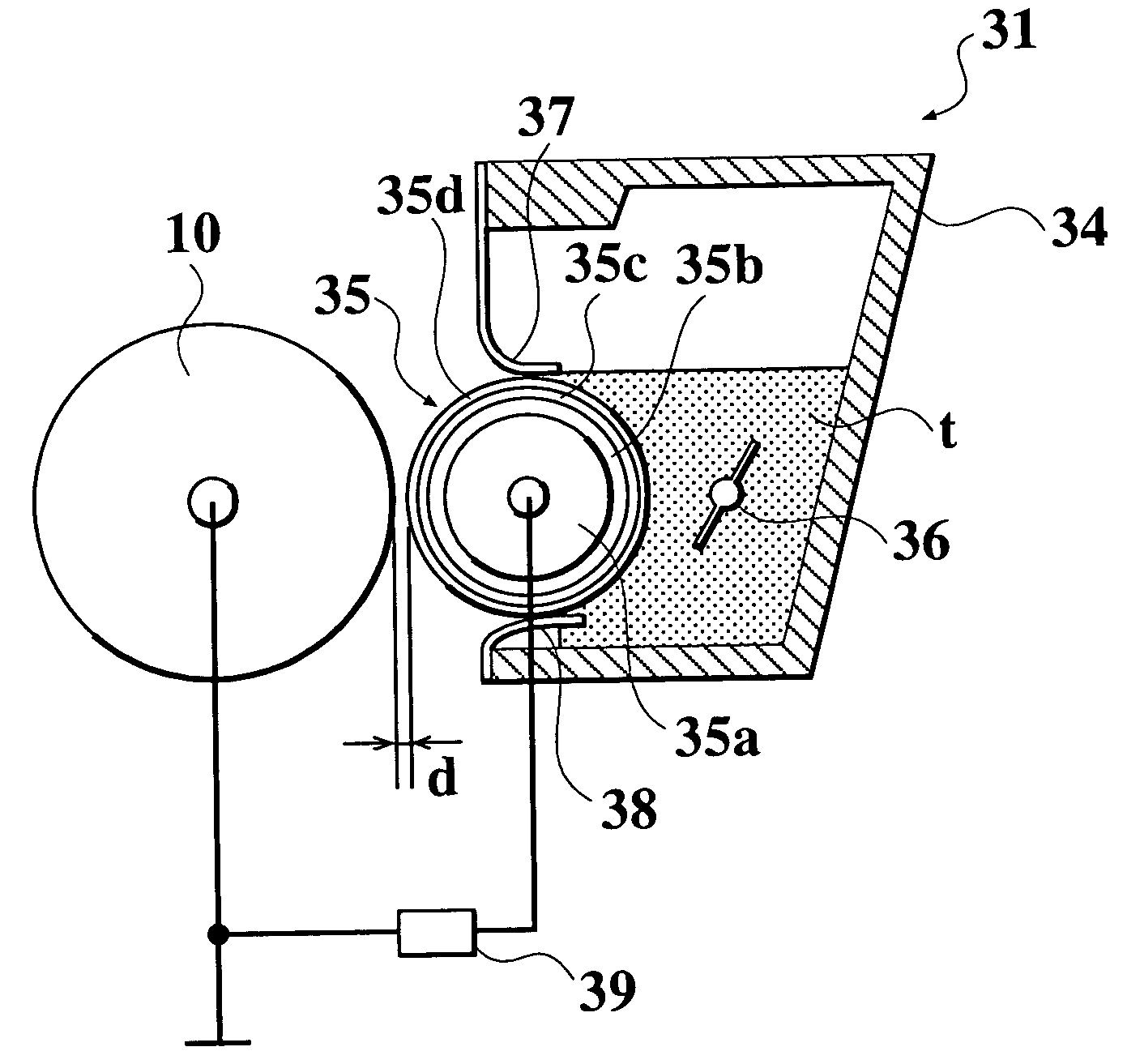
[0282] According to the image forming method using the non-magnetic single component developer, an electrostatic latent image formed on a surface of an electrostatic latent image carrier is developed by the non-magnetic single component development system using a toner carried and transferred by a toner carrier with which a toner layer limiting member for limiting the amount of the toner on the surface of the toner carrier has been brought into pressure contact, then the toner forming a toner image which is visualized by the development on the surface of the electrostatic latent image carrier, is transferred to an image support (hereinafter referred to as the "recording member"), such as paper, and the transferred toner is thermally fixed, whereby a visible image is formed on the recording member.
[0283] FIG. 2 is a diagram schematically showing an example of the arrangement of an image forming apparatus used in the present invention.
[0284] The image forming apparatus is comprised of an electrostatic latent image carrier (hereinafter simply referred to as "the image carrier") 10 formed by a photoreceptor drum rotating clockwise as viewed in FIG. 2 (in a direction indicated by an arrow in FIG. 2), a charging brush 11 for uniformly charging a surface of the image carrier 10 to a predetermined potential, an optical laser scanning system 20 which contains, for example, a laser diode, a polygon mirror, and an f.theta. optical element, and executes scanning exposure by a laser beam to thereby form an electrostatic latent image on the surface of the image carrier 10 based on image information of an image to be formed on the image carrier 10 uniformly charged, a developing device 30 for developing the electrostatic latent image formed on the surface of the image carrier 10 to thereby form a toner image, an endless intermediate transfer belt 40 to which the toner image formed on the image carrier 10 is primarily transferred by urging operation of a primary transfer roller 41, a secondary transfer roller 43 for transferring the primary transfer toner image primarily transferred on the intermediate transfer belt 40 onto a recording member S, such as paper, by urging operation thereof, at a portion of the intermediate transfer belt 40, supported by a support roller 42, and a fixing device 70 that includes a heating roller 71 formed by a tension roller provided with a halogen heater, a fixation belt 73 stretched around a fixation roller 74 formed by a drive roller, and a pressure roller 75 brought into pressure contact with the fixation roller 74 via the fixation belt 73, and fixes the toner image transferred on the surface of the recording member S.

Problems solved by technology

Therefore, to give a necessary amount of electric charge to the toner by the frictional charge, a large shearing stress is inevitably applied to the toner and can crush the toner particles.
A problem that the fine toner particles caused by the crush are attached to components of an image forming apparatus, such as the toner carrier, to degrade the image formability of the toner, is caused.
Therefore, if the toner obtained by the suspension polymerization method is used as the non-magnetic single component developer, there is a fear of generation of a development ghost.
However, even when the toner obtained by the association method is used as the non-magnetic single component developer, there can occur an image defect, such as hollowing of an image obtained, and fogging.
After all, it is impossible to obtain a high-quality image, with stability.
When the adhesive stress exceeds 1200 N / m.sup.2, there is a fear that transferability is degraded, thereby causing hollowing of an image obtained.
However, if the external additive is added to the toner in an excessively large amount, increased scattering of toner may degrade the image quality and contamination of the electrostatic latent image carrier may be caused by transfer of the external additive.
When the surface coverage is smaller than 40%, the advantageous effect of the external additive is not sufficiently exhibited in a toner obtained, whereas when the surface coverage exceeds 100%, there occurs liberation of the external additive, which can cause damage to an electrostatic latent image carrier.
When the mount of the polymerization initiator added is too small, polymerization reaction cannot be sufficiently carried out, so that there is a fear that the monomer remains in an reaction product obtained.
On the other hand, when the mount of the polymerization initiator added is too large, there is a fear that decomposed products of the polymerization initiator remain in an reaction product obtained, which hinders the toner from having an appropriate electric chargeability, and further, the rate of the polymerization reaction is increased to reduce the molecular weight of the reaction product obtained.
When the ration of sticking is smaller than 25%, a degree of sticking of the inorganic fine particles to the core resin fine particles is lowered, causing liberation of the inorganic fine particles which exist on the surfaces of the core resin fine particles, and if composite fine particles are repeatedly used for a long time period, the liberation of inorganic fine particles can cause undesired damage to the electrostatic latent image carrier.
This is because when the atmospheric temperature is excessively high, coalescence of core resin fine particles is caused.
On the other hand, when internal temperature is lower than the temperature Tg by 30.degree. C. or more, an excessively large amount of the energy is required for causing the inorganic fine particles to be stuck to the core resin fine particle, thereby increasing the energy of collision of particles.
This is because when the rotational speed is too high, the mixing-with-stirring process accelerates burial of the external additive into the colorant particles, resulting in the increased adhesive stress of a toner obtained.
When the mass average particle diameter of the fine particles of the colorant is smaller than 30 nm, the floating of colorant particles in the water-base medium is increased, and when the mass average particle diameter exceeds 500 nm, the colorant particles are not properly dispersed in the water-base medium and made liable to settle out, so that it is sometimes difficult to introduce the colorant into the toner particles.
Under such conditions, the colorant particles unfavorably remain free in the water-base medium without being taken into the toner particles.
Further, when the dried toner particles are aggregated to each other by a weak interparticle attracting force, the aggregate may be crushed.
When the arithmetic mean roughness Ra on the toner carrier 35 exceeds 0.8 .mu.m, the amount of toner taken in by the toner carrier 35 is large, which reduces electrostatic chargeability in a limiting section for limiting the amount of toner, using the toner layer limiting member, so that there is a fear of fogging being caused due to defective charge.
On the other hand, when the arithmetic mean roughness Ra on the surface of the toner carrier 35 is smaller than 2.5 .mu.m, the amount of toner taken in by the toner carrier 35 is small, so that there is a fear of unevenness of an image and faulty following operation being liable to occur.
When the ten-point average roughness Rz on the toner carrier 35 is smaller than 5.0, latitude in image leakage and unevenness of density in the developing step can be narrowed, whereas when the ten-point average roughness Rz in the toner carrier 35 exceeds 15.0, the latitude in image leakage and unevenness of density in the developing step are widened, but this necessitates increase in the capacity of high voltage power supply, which can result in an increase in manufacturing costs of the toner.

Method used


Image

  • Toner and image forming method
  • Toner and image forming method
  • Toner and image forming method

Examples


preparation examples

C1 to C4 of Colorant Particles

[0340] Colorant particles (hereinafter also referred to as "the colorant particles (C1) to (C4)") were obtained in the same manner as in Preparation Example K1 except that a whole amount of the colorant dispersion (4) was used in place of the whole amount of the colorant dispersion (1), the growth of particles was stopped when the volume average particle diameter thereof became equal to a corresponding size shown in Table 2, and the stirring rotation rate, liquid temperature, and heating-with-stirring time period for the aging treatment were set to conditions shown in Table 1.

[0341] Characteristics of the obtained colorant particles (C1) to (C4) were checked. The results of the check are shown in Table 2 and Table 3.

1TABLE 1 STIRRING STIRRING ROTATION LIQUID TIME UNDER RATE TEMPERATURE HEATING (rpm) (.degree. C.) (h) COLORANT 120 90 8 PARTICLE K1 COLORANT 140 90 8 PARTICLE K2 COLORANT 150 88 6 PARTICLE K3 COLORANT 120 95 10 PARTICLE K4 COLORANT 120 90 8...

preparation example c5

of Colorant Particles: Preparation Example of Comparative Colorant Particles

[0345] Colorant particles (hereinafter referred to as "the colorant particles (C5)") having a volume average particle diameter shown in Table 2 were obtained in the same manner as in Preparation Example K5 except that 10 g of phthalocyanine cyan pigment "C.I. pigment blue 15:3" was used in place of 10 kg of carbon black.

2TABLE 2 RATIO OF COLORANT PARTICLES ARITHMETIC COEFFICIENT OF RATIO OF HAVING VOLUME COLORANT MEAN VALUE VARIATION ROUNDED PREDETERMINED AVERAGE PARTICLE OF SHAPE OF SHAPE COLORANT PARTICLE PARTICLE NUMBER FACTOR FACTOR PARTICLES DIAMETER DIAMETER COLORANT 1.30 9% 91 NUMBER % 7.6 VOLUME % 6.5 .mu.m PARTICLE K1 COLORANT 1.40 12% 88 NUMBER % 6.1 VOLUME % 6.6 .mu.m PARTICLE K2 COLORANT 1.45 15% 83 NUMBER % 9.1 VOLUME % 6.6 .mu.m PARTICLE K3 COLORANT 1.56 17% 81 NUMBER % 9.6 VOLUME % 6.6 .mu.m PARTICLE K4 COLORANT 1.65 22% 42 NUMBER % 11.8 VOLUME % 6.5 .mu.m PARTICLE K5 COLORANT 1.32 10% 92 NUMB...

preparation example 1

of Toner Carrier

[0369] An aluminum roller with an external diameter of 14 mm was prepared as a conductive substrate, set in an elastic layer forming mold, and an elastic layer coating liquid, referred to hereinafter, was injected around the periphery of the roller in the mold, and cured by heating at 120.degree. C. for 5 minutes. Further, a composite was obtained by heating the aluminum roller and the elastic layer coating liquid with the mold removed therefrom at 150.degree. C. for one hour, and a surface of the composite was polished by a traverse-type cylindrical grinder, whereby an elastic layer having a thickness of 1 mm was formed on the periphery of the aluminum roller.

[0370] After the elastic layer formed on the outer periphery of the aluminum roller was subjected to a surface treatment using a silane coupling agent, an intermediate layer coating liquid, referred to hereinafter, was sprayed onto the surface of the elastic layer to form a coating, and the coating was dried, w...


PUM


Abstract

A toner includes a resin and a colorant; wherein the toner is obtained by carrying out a step of salting-out / fusing resin particles and colorant particles in a water-base medium, the toner satisfying the following relationship: 0.88<=F25 / F50<=1.0, where F25 represents an adhesive stress at a toner temperature of 25° C., and F50 represents an adhesive stress at a toner temperature of 50° C.

Description

[0001] 1. Field of the Invention[0002] The present invention relates to a toner, and an image forming method.[0003] 2. Description of the Related Art[0004] Conventionally, to form a color image e.g. by electronic photography, for example, a non-magnetic single component development system in which a latent image formed on an electrostatic latent image carrier is developed by a toner carried and transferred by a toner carrier to which a toner layer limiting member for limiting the amount of the toner on the surface of the toner carrier is pressed, is employed.[0005] In the non-magnetic single component development system, when the toner layer limiting member limits the amount of toner on the toner carrier, the toner is frictionally charged. Thereby, the toner is transferred by the toner carrier. Therefore, to give a necessary amount of electric charge to the toner by the frictional charge, a large shearing stress is inevitably applied to the toner and can crush the toner particles. A...

Claims


Application Information

Patent Timeline
Patent Type & Authority Applications(United States)
IPC IPC(8): G03G9/08G03G9/087G03G9/097G03G15/08
CPCG03G9/0804G03G9/0819G03G9/09725G03G9/097G03G9/09708G03G9/0821
Inventor YAMANOUCHI, TAKAOUCHIDA, MASAFUMIANNO, MASAHIROSEKIGUCHI, YOSHITAKANAKAMURA, MINORU
Owner KONICA MINOLTA INC
Learn More