System and method for reducing emission from a combustion engine

a technology of combustion engine and emission reduction, which is applied in the direction of machines/engines, mechanical equipment, non-fuel substance addition to fuel, etc., can solve the problems of limiting to lean combustion, and reducing the production of nox, so as to reduce the emission from the combustion engine system

a technology of combustion engine and emission reduction, which is applied in the direction of machines/engines, mechanical equipment, non-fuel substance addition to fuel, etc., can solve the problems of limiting to lean combustion, and reducing the production of nox, so as to reduce the emission from the combustion engine system

US7261064B2Inactive Publication Date: 2007-08-28GENERAL ELECTRIC CO

Image

  • System and method for reducing emission from a combustion engine
  • System and method for reducing emission from a combustion engine
  • System and method for reducing emission from a combustion engine

Examples


Embodiment Construction

[0015]A combustion engine system comprises a plurality of cylinders configured to combust a mixed fuel to produce an exhaust gas, and at least one reforming cylinder configured to receive a first portion of a fuel and deliver a reformed hydrogen-containing gas. The hydrogen-containing gas is introduced into a second portion of the fuel to form the mixed fuel to reduce emission from the combustion engine system.

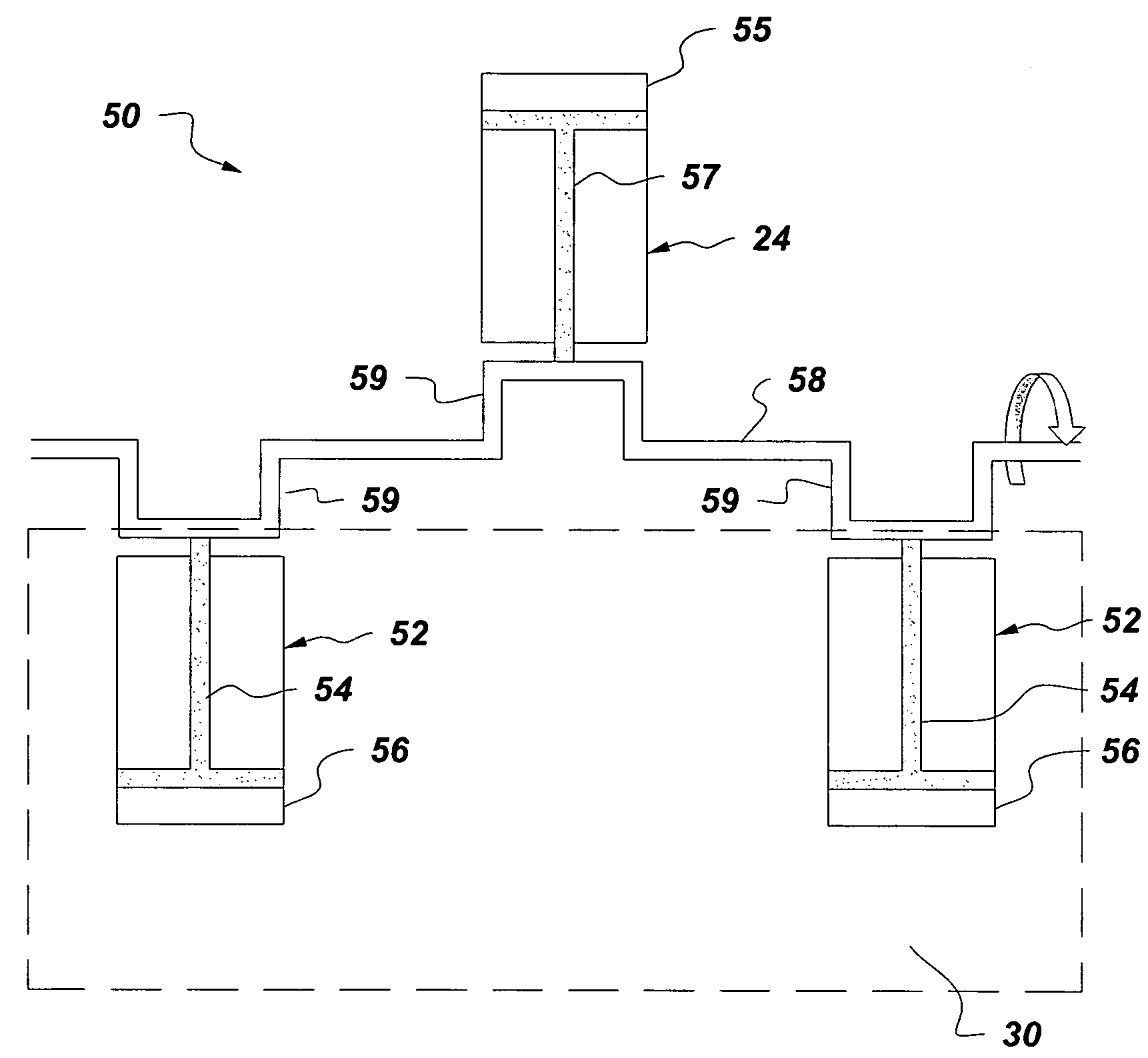
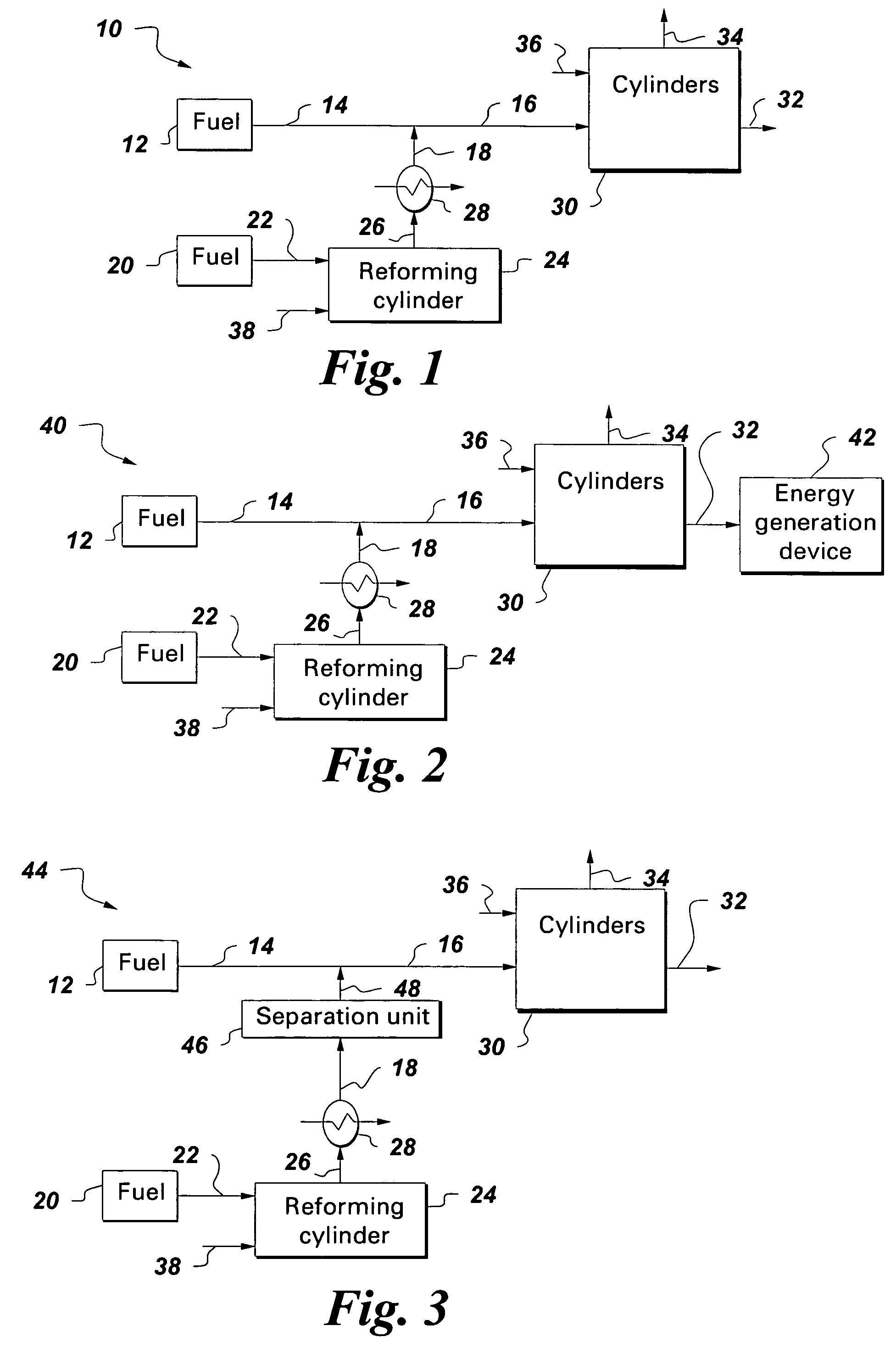
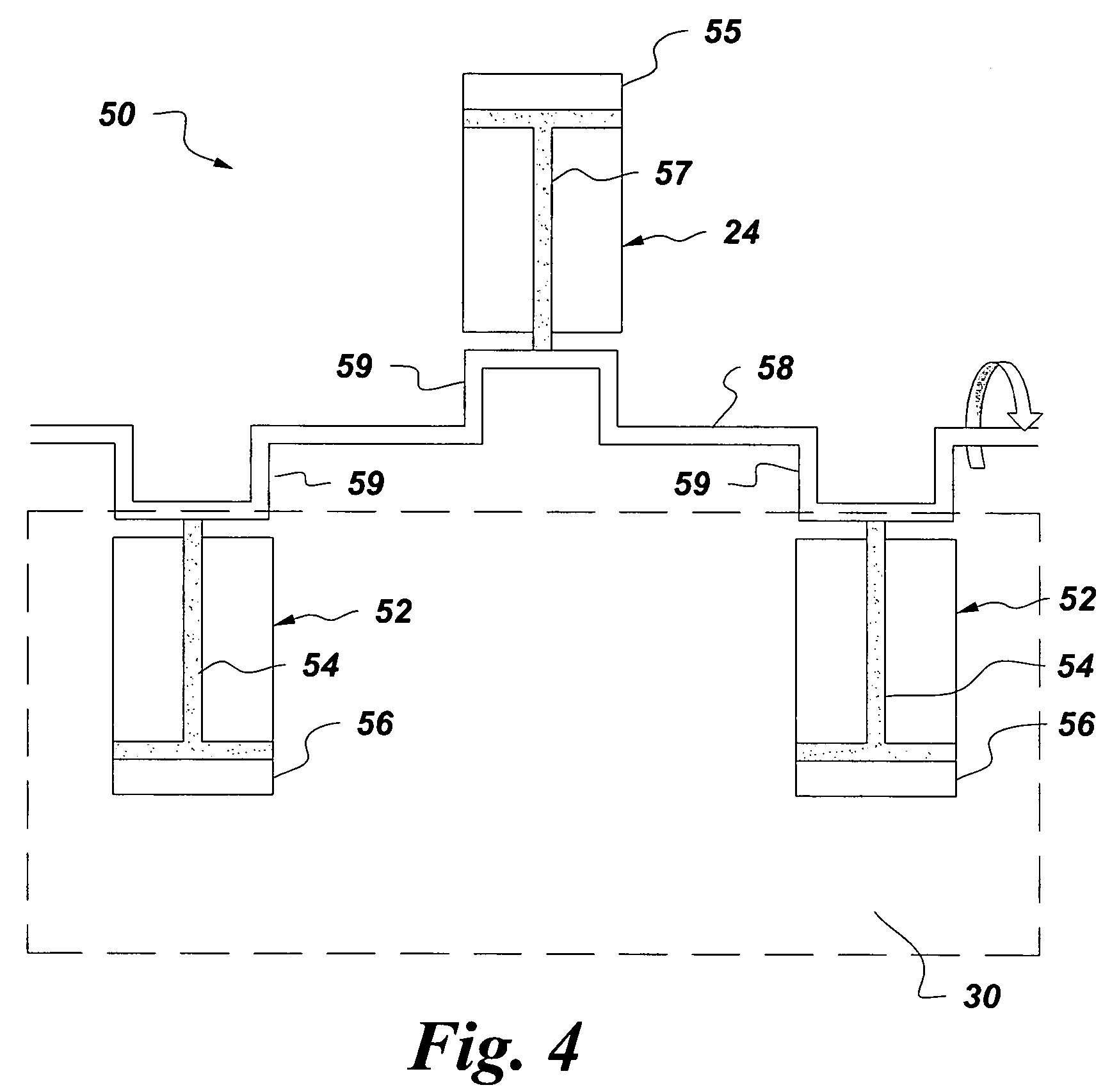
[0016]FIG. 1 illustrates an exemplary combustion engine system 10 comprising a plurality of cylinders 30. The plurality of cylinders 30 are configured to combust a mixed fuel 16 to produce an exhaust gas 34 and work 32. The combustion engine system 10 comprises at least one reforming cylinder 24 configured to receive a first portion of a fuel 22 from a fuel source 20 and deliver a reformed hydrogen-containing gas 26. The hydrogen-containing gas 26 is introduced into a second portion of the fuel 14 from another fuel source 12 to form the mixed fuel 16. The mixed fuel 16 is comb...


PUM


Abstract

A combustion engine system comprises a plurality of cylinders configured to combust a mixed fuel to produce an exhaust gas and at least one reforming cylinder configured to receive a first portion of a fuel and deliver a reformed hydrogen-containing gas. The hydrogen-containing gas is introduced into a second portion of the fuel to form the mixed fuel to reduce emission from the combustion engine system.

Description

BACKGROUND OF THE INVENTION[0001]The present disclosure relates generally to a system and method for reducing emissions from a combustion engine and particularly to a system and method for reducing emissions from a combustion engine by enriching the combustion fuel with hydrogen-containing gas.[0002]Current technologies for reducing emission of toxic gases, such as NOx from reciprocating engines using natural gas as fuel, rely on lean combustion. Lean combustion reduces the peak temperatures within the cylinders in the engine, and hence reduces the production of NOx. Gases such as NOx are formed by reactions between nitrogen and oxygen in air that is used for combustion in an engine. Formation of NOx strongly depends on the temperature of combustion. Due to low flame speed of natural gas, there are limits to lean combustion without affecting combustion stability. Other methods of NOx reduction involve use of after-treatment technologies that are costly and can have reliability issue...

Claims


Application Information

Patent Timeline
28 Aug 2007
Publication
US7261064B2
IPC
F02B43/08
CPC
F02M25/10; F02D19/0644; F02D19/0671; F02D19/081; Y02T10/121; Y02T10/36; C01B3/366; C01B2203/0255
Inventors
BHAISORA, SHAILESH SINGH; BOWMAN, MICHAEL JOHN