Cargo aircraft

a cargo aircraft and aircraft technology, applied in the direction of fuselages, weapons launchers, transportation and packaging, etc., can solve the problems of air cargo being excluded from the participation of intermodal cargo systems, volume instead of weight creating the limiting factor in the design of intermodal containers, and limited intermodal containers

Active Publication Date: 2007-08-28
BIOSPHERE AEROSPACE
View PDF35 Cites 58 Cited by
  • Summary
  • Abstract
  • Description
  • Claims
  • Application Information

AI Technical Summary

Benefits of technology

[0005]The present invention is directed to an aircraft having a beam structure to receive at least one rigid cargo container with mounts detachably integrating the at least one rigid cargo container as part of the beam structure to provide structural rigidity to the aircraft in flight.
[0013]In an eighth separate aspect of the present invention, the aircraft is a drone. As a drone, efficient low speed and, correspondingly, longer flights without crew are cost effective and advantageous.

Problems solved by technology

Thus, volume instead of weight creates the limiting factor in the design of intermodal containers.
As such, intermodal containers are limited by the dimensions allowed by highway infrastructures.
However, air cargo has generally been excluded from participation in intermodal cargo systems.
Cylindrical fuselages and lack of large access ports thereto in such passenger aircraft limit the use of such aircraft for truly intermodal cargo systems.
Military transports are also not particularly compatible with intermodel cargo systems as they are designed for oversized cargo such as rolling equipment, e.g., tanks and trucks, and palletized, irregularly shaped cargo.
The inability of aircraft to participate in intermodal container cargo systems has been disadvantageous to international commerce.
However, air cargo systems remain both expensive and inconvenient to intermodal shipping.

Method used


Image

  • Cargo aircraft
  • Cargo aircraft
  • Cargo aircraft

Examples


Embodiment Construction

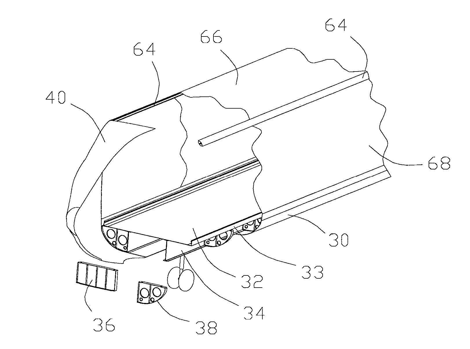
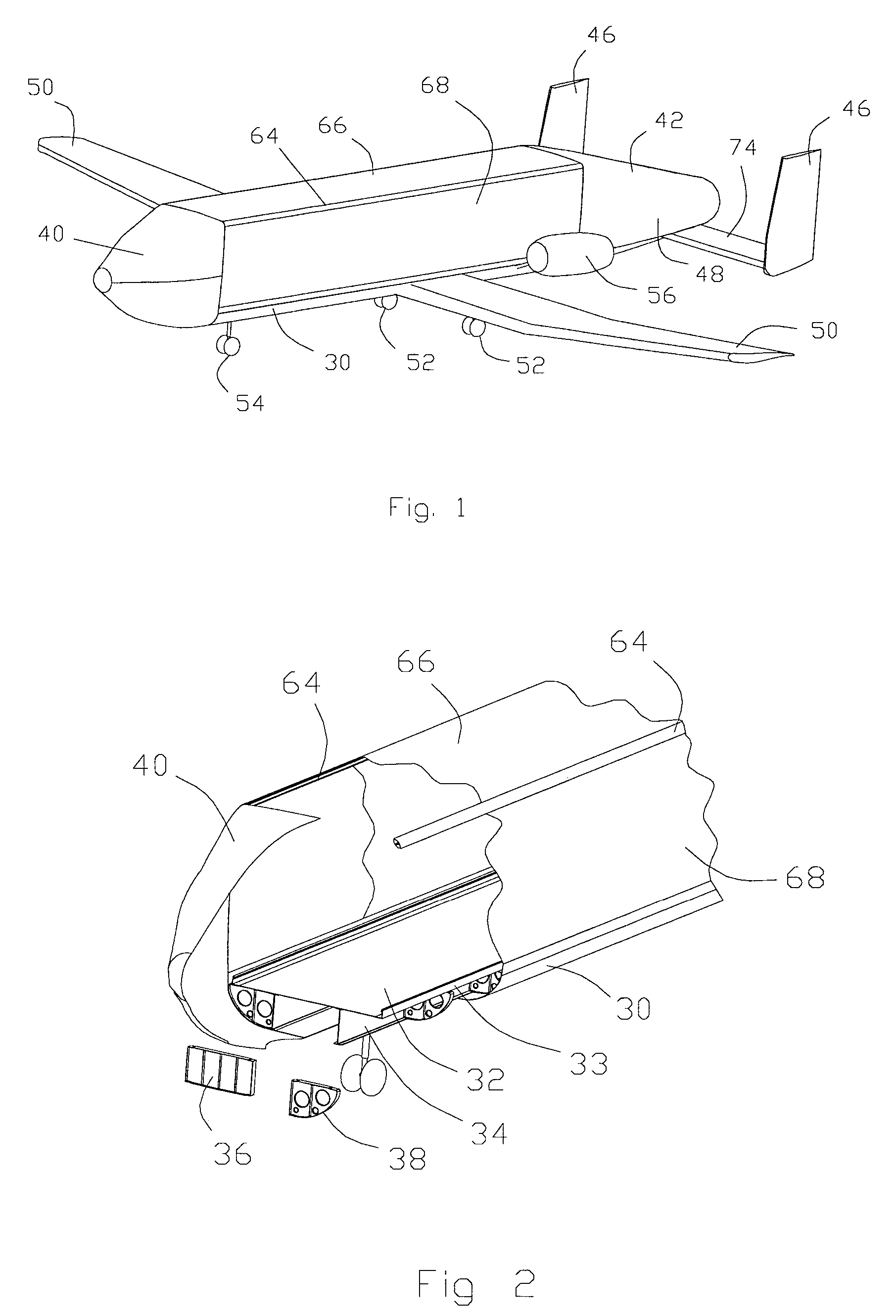
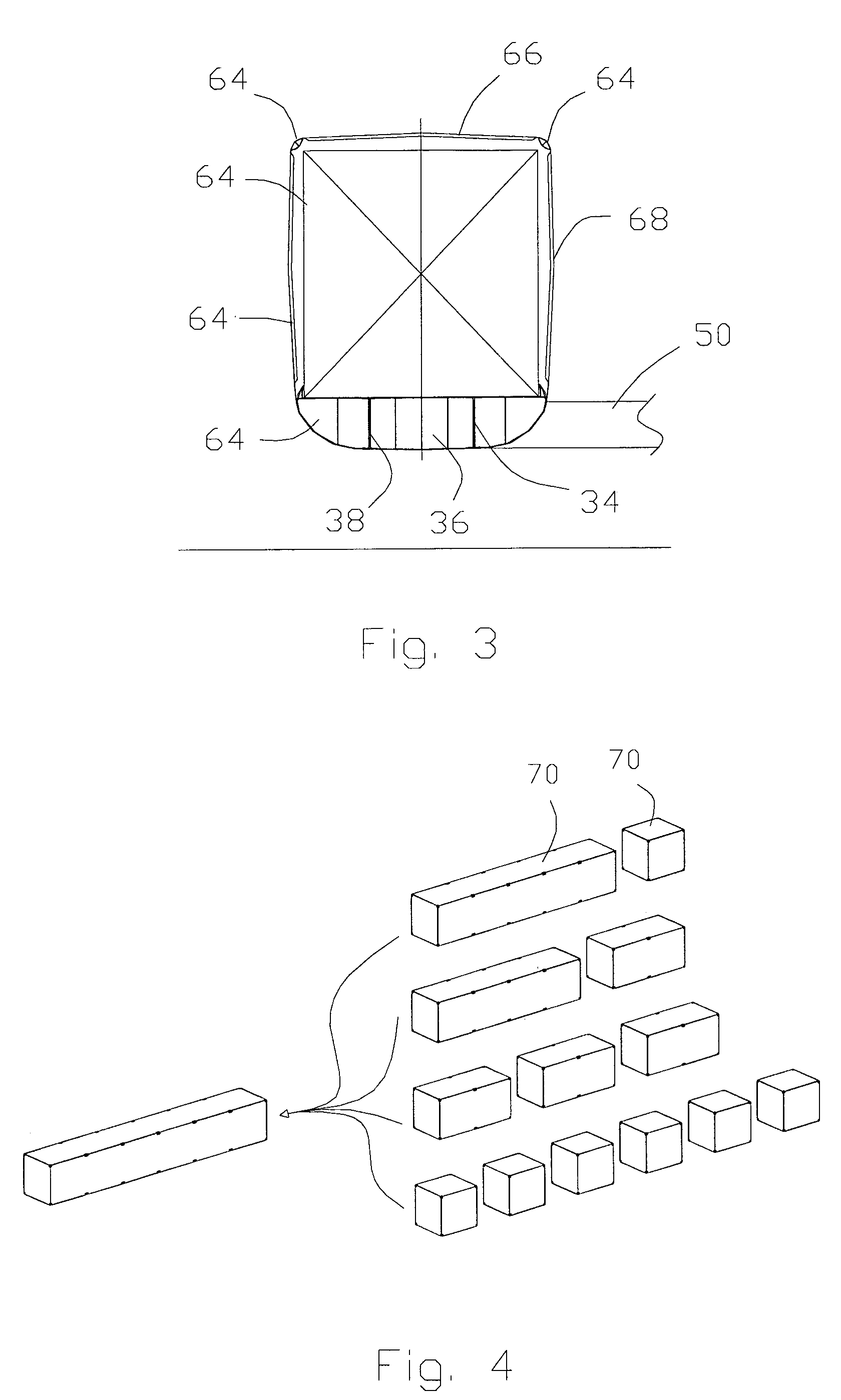
[0047]FIG. 1 illustrates a first aircraft design with an integrating and supporting beam structure 30 having two ends. The details of the beam structure 30 are better illustrated in FIGS. 2 and 3. The beam structure 30 includes a floor 32 which may include rollers and / or antifriction devices to facilitate longitudinal movement of a cargo container along the surface of the floor 32. Restraining flanges 33 run along each longitudinal side of the floor 32. In addition to the floor 32, the beam structure 30 includes I-beams 34 with bulkheads 36, 38 positioned periodically along the beam structure 30 and affixed to the floor 32 and the I-beams 34. The beam structure 30 becomes a rigid structure which is preferably sufficient to support the aircraft in flight when empty but cannot support the aircraft in flight when loaded.

[0048]A forward fuselage 40 is located at one end of the beam structure 30. The forward fuselage 40 is shown to be that of a drone with no cockpit. Since the Shuttle SR...


PUM


Abstract

An aircraft for carrying at least one rigid cargo container includes a beam structure with a forward fuselage attached to the forward end of the beam structure and an empennage attached to the rearward end of the beam structure. Wings and engines are mounted relative to the beam structure and a fairing creates a cargo bay able to receive standard sized intermodal cargo containers. Intermodal cargo containers of light construction and rigid structure are positioned within the cargo bay and securely mounted therein. The beam structure is designed to support flight, takeoffs and landings when the aircraft is empty but requires the added strength of the containers securely mounted to the beam structure when the aircraft is loaded. The aircraft is contemplated to be a drone.

Description

BACKGROUND OF THE INVENTION[0001]The field of the present invention is cargo aircraft for transporting modular containers.[0002]The basic unit for transporting goods has been the truck. Being the basic unit, the truck has defined limitations on intermodal containers that can typically be transported by ships, trains and trucks. Much of commerce today for which intermodal containers are most convenient are high volume, low weight products, computers being one example. Thus, volume instead of weight creates the limiting factor in the design of intermodal containers. As such, containers have grown to the maximum volume capacity of the basic unit, the truck. As such, intermodal containers are limited by the dimensions allowed by highway infrastructures.[0003]The aforementioned intermodal containers have greatly facilitated and lowered the cost of cargo transportation. However, air cargo has generally been excluded from participation in intermodal cargo systems. Aircraft of a size capabl...

Claims


Application Information

Patent Timeline
Patent Type & Authority Patents(United States)
IPC IPC(8): B64C1/22
CPCB64C1/00B64C1/065B64C1/10B64C39/02B64C39/024B64C1/061Y02T50/433B64C2001/0072B64C2201/021B64C2201/048B64C2201/086B64C2201/104B64C2201/128B64C2201/162B64C2201/167B64C2211/00B64U50/12B64U70/60B64U10/25B64U30/10B64U2101/60B64U50/15B64U50/14Y02T50/40
Inventor HELOU, JR., ELIE
Owner BIOSPHERE AEROSPACE
Why Eureka
Try Eureka