Cam lock for vehicle seating

a technology for vehicle seats and cam locks, which is applied in the field of cam locks for vehicle seats, can solve the problems of relative complexity and high cost compared to purely mechanical arrangements, and achieve the effect of low manufacturing cos

Active Publication Date: 2007-08-28
BE AEROSPACE INCORPORATED
View PDF25 Cites 11 Cited by
  • Summary
  • Abstract
  • Description
  • Claims
  • Application Information

AI Technical Summary

Benefits of technology

[0003]Therefore, it is an object of the invention to provide a locking apparatus for a moveable portion of a passenger seat which allows the seat to be selectively locked in a desired position.
[0006]It is another object of the invention to provide a locking apparatus that is inexpensive to manufacture.
[0015]According to another preferred embodiment of the invention, the first pair of cams protrude from the housing when in the lock position to engage and prevent the housing from sliding within the track.

Problems solved by technology

While these type of devices provide the desired adjustability, they are relatively complex and expensive compared to purely mechanical arrangements.

Method used


Image

  • Cam lock for vehicle seating
  • Cam lock for vehicle seating
  • Cam lock for vehicle seating

Examples


Embodiment Construction

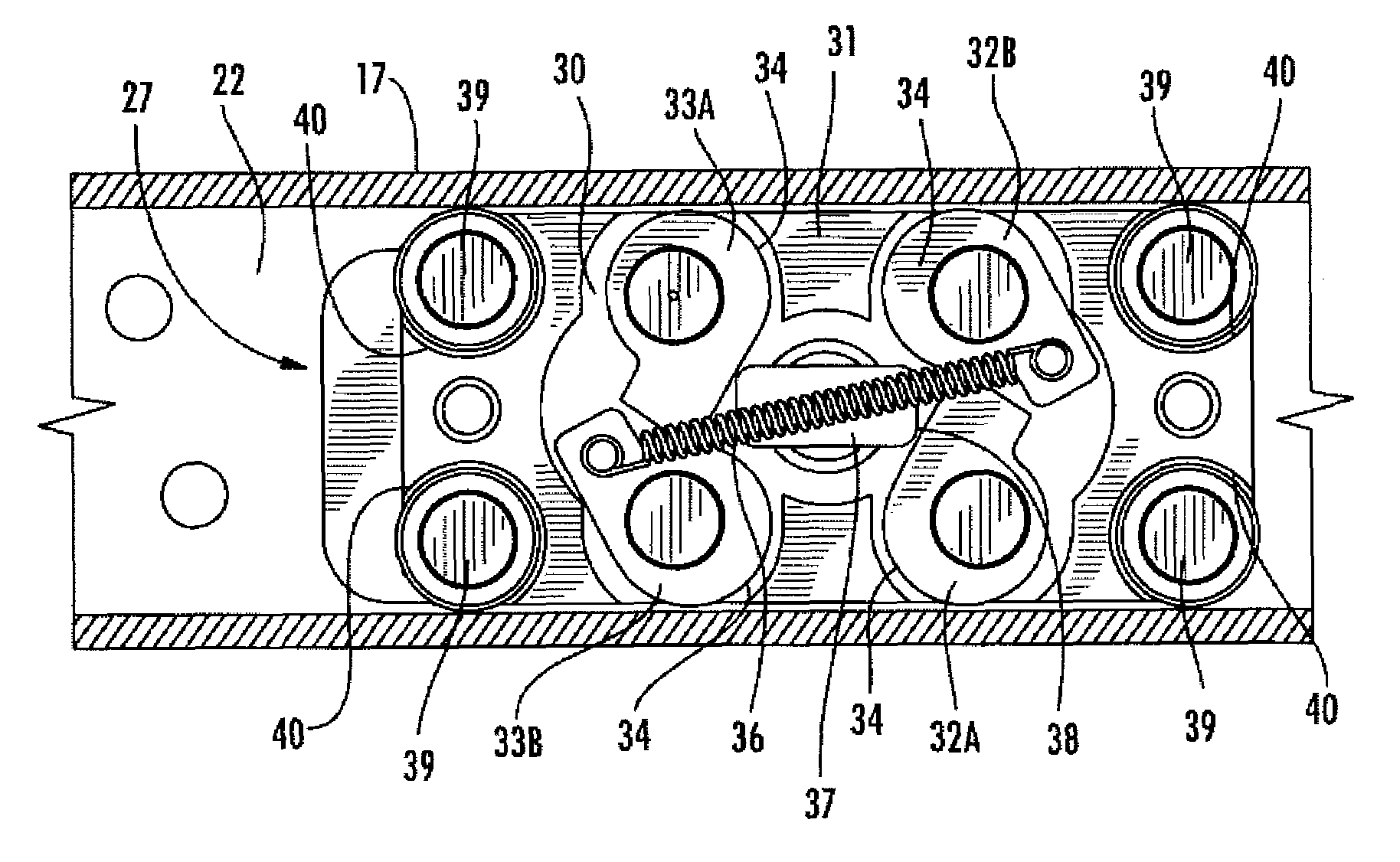
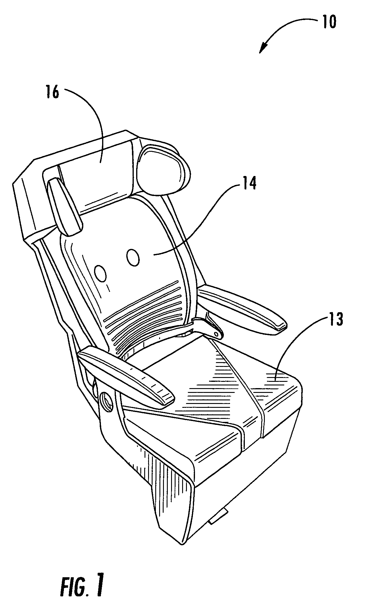
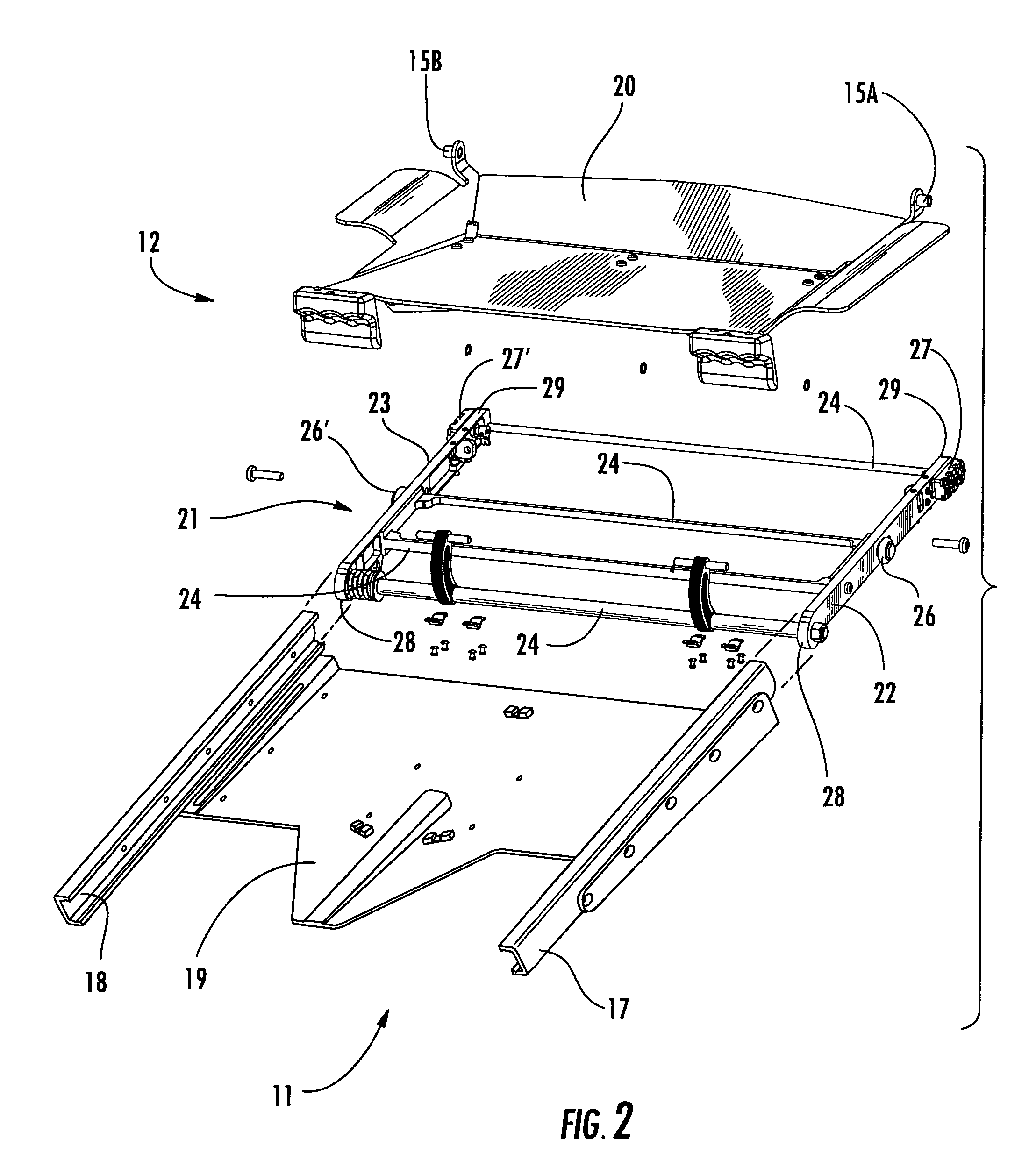
[0030]Referring now specifically to the drawings, an exemplary passenger seat constructed according to an embodiment of the present invention is illustrated in FIGS. 1-3 and shown generally at reference numeral 10. The seat 10 has a seat frame 11 for being attached to the deck of an aircraft (a portion of which is shown in FIG. 2) and includes a seat pan assembly 12 slidably attached to the seat frame 11, a seat bottom 13, a seat back 14 pivotally attached to a pair of pivots 15A and 15B of the seat pan assembly 12, and a headrest 16. The seat frame 11 includes two spaced-apart, longitudinal, inward-facing C-shaped tracks 17 and 18 connected by a plate 19. The seat pan assembly 12 includes a seat pan 20 attached to a seat pan frame assembly 21 which includes a pair of spaced-apart rails 22 and 23 connected by a plurality of cross-members 24. Rollers 26 and 26′ and a locking apparatuses 27 and 27′ are positioned on an outside surface of the rails 22 and 23 respectively, and are sized...


PUM


Abstract

A locking apparatus for a moveable component of an aircraft seat. The locking apparatus includes a housing for being slidably received in a track, a first pair of opposed cams pivotally mounted in the housing, and a release member. The cams are moved between a lock position where the cams prevent the housing from sliding within the track and a release position. The release member is selectively moveable between a first position where the cams are maintained in the lock position and a second position where the cams are maintained in the release position.

Description

BACKGROUND OF THE INVENTION[0001]This invention relates generally to vehicle seating and more particularly to a locking apparatus for a moveable component of an aircraft seat.[0002]Seating units, particularly those in aircraft, are often provided with one or more components which are moveable so that a passenger seated therein can be comfortably supported in various positions. For example, the bottom of the seat may be translatable fore and aft. In order to provide the desired crash-worthiness, these moveable components must be securely locked in position when not actually being moved by the passenger. They must also be easy and convenient for the passenger to move when necessary, and they must withstand repeated and sometimes rough usage. Various prior art seats include electric motors or actuators to operate the moveable components, or pneumatic or hydraulic elements such as “hydrolocks”. While these type of devices provide the desired adjustability, they are relatively complex an...

Claims


Application Information

Patent Timeline
Patent Type & Authority Patents(United States)
IPC IPC(8): A47C1/02
CPCA47C1/02
Inventor DOWTY, MARK BRIANHAUSHALTER, WILLIAM EDWARD
Owner BE AEROSPACE INCORPORATED
Why Eureka
Try Eureka