Optical connector having shielding mechanism

a technology of optical connectors and shielding mechanisms, which is applied in the direction of optics, instruments, optical light guides, etc., can solve the problems of large device size and light leakage before the connectors are connected to each other, and achieve the effect of reducing the size of the device and reducing the space for the housing of the shutter

Inactive Publication Date: 2007-08-28
HIROSE ELECTRIC GROUP +2
View PDF8 Cites 12 Cited by
  • Summary
  • Abstract
  • Description
  • Claims
  • Application Information

AI Technical Summary

Benefits of technology

[0010]To achieve the above objects, the present invention is an optical connector device comprising a first optical connector and a second optical connector, wherein when shutters for shutting out light from the optical connectors are collided with each other, the shutters move to positions where they do not shut out the light, whereby the first optical connector and the second optical connector are connected to each other; and after moving, the shutter of the first optical connector and the shutter of the second optical connector are inserted into the second optical connector while remaining contacting each other. Thereby, there can be provided the optical connector device which prevents leakage of light until right before the connectors are connected to each other, and the size of the device can be reduced by a reduction in the size of space for housing the shutters.
[0011]Further, the present invention is an optical connector device that optically connects a first optical connector and a second optical connector to each other by colliding them with each other in their longitudinal directions, wherein shutters which are constantly biased to be positioned at closing positions where they shut out light emitted from optical fibers disposed in the optical connectors and which can move in directions intersecting the longitudinal directions are provided on the sides of the first optical connector and second optical connector on which they are collided with each other; and when the shutter of the first optical connector and the shutter of the second optical connector are collided with each other, the shutter of the first optical connector and the shutter of the second optical connector are moved, against the biasing force, to opening positions where they do not shut out light, by force given by one of the shutters to the other shutter, whereby the first optical connector and the second optical connector can be connected to each other. Thereby, there can be provided the optical connector device which prevents leakage of light until right before the connectors are connected to each other.
[0012]The above optical connector device may be such that the shutter of the first optical connector and the shutter of the second optical connector have inclined surfaces that slide on each other when the shutters are collided with each other and the inclined surfaces are in a complementary relationship. Further, in the above optical connector device, the inclined surfaces may have a nearly triangular cross section which has a portion projecting at least toward the opposing shutter in the longitudinal direction. Thereby, movement of the shutters can be further smoothed.

Problems solved by technology

However, the above optical connector has a problem that light leaks before the connectors are connected to each other because the shutters are already moved from the closing position to the opening position upon insertion of the connectors into the adapter.
Further, there is also a problem that since the shutters are pushed upward in the adapter, considerable space is required for housing the shutters, thereby making the size of the device large.

Method used


Image

  • Optical connector having shielding mechanism
  • Optical connector having shielding mechanism
  • Optical connector having shielding mechanism

Examples


Embodiment Construction

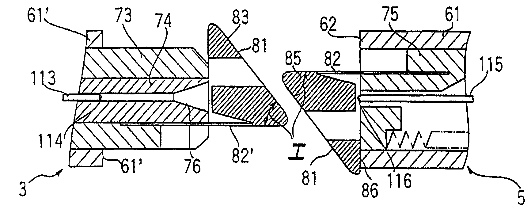
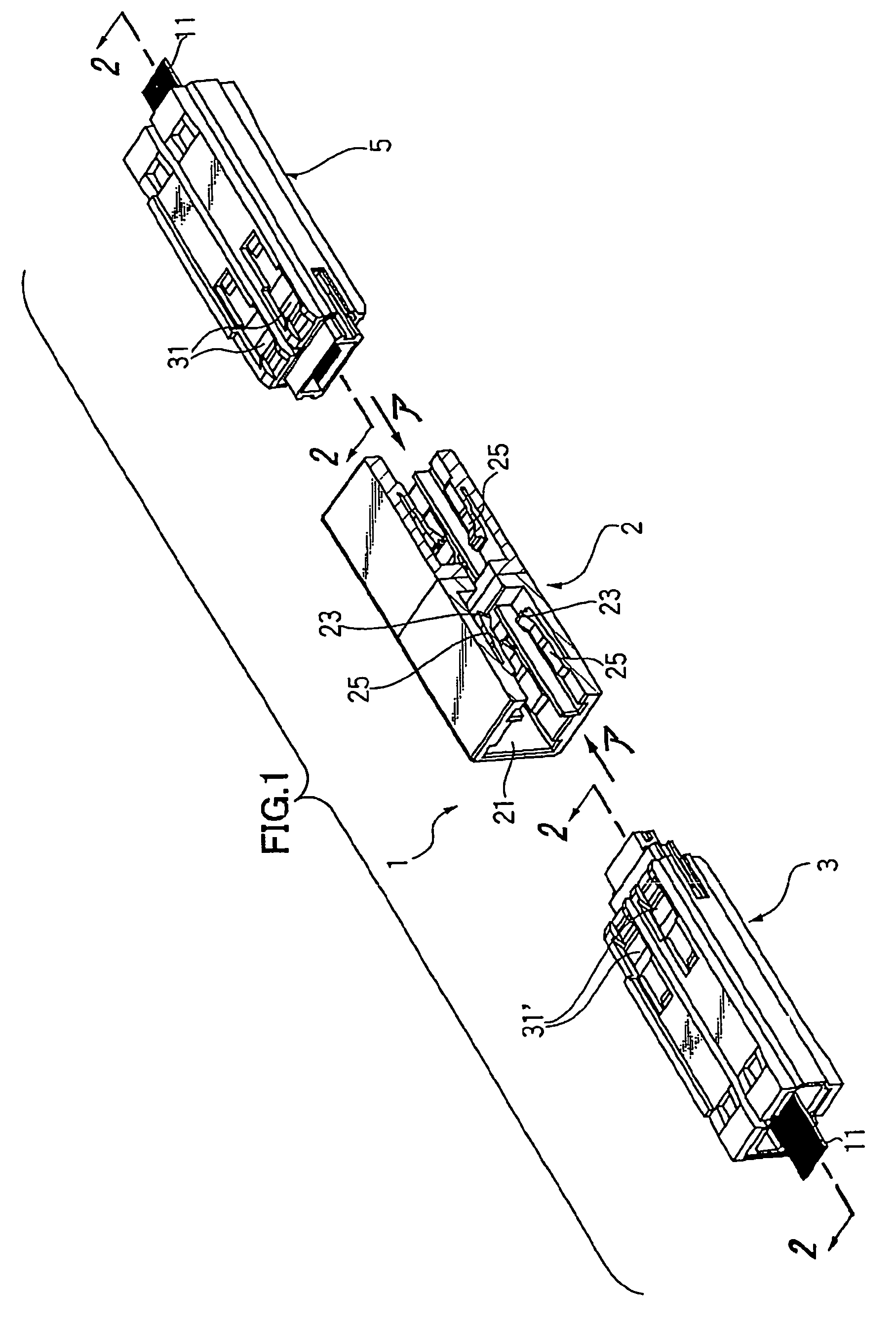
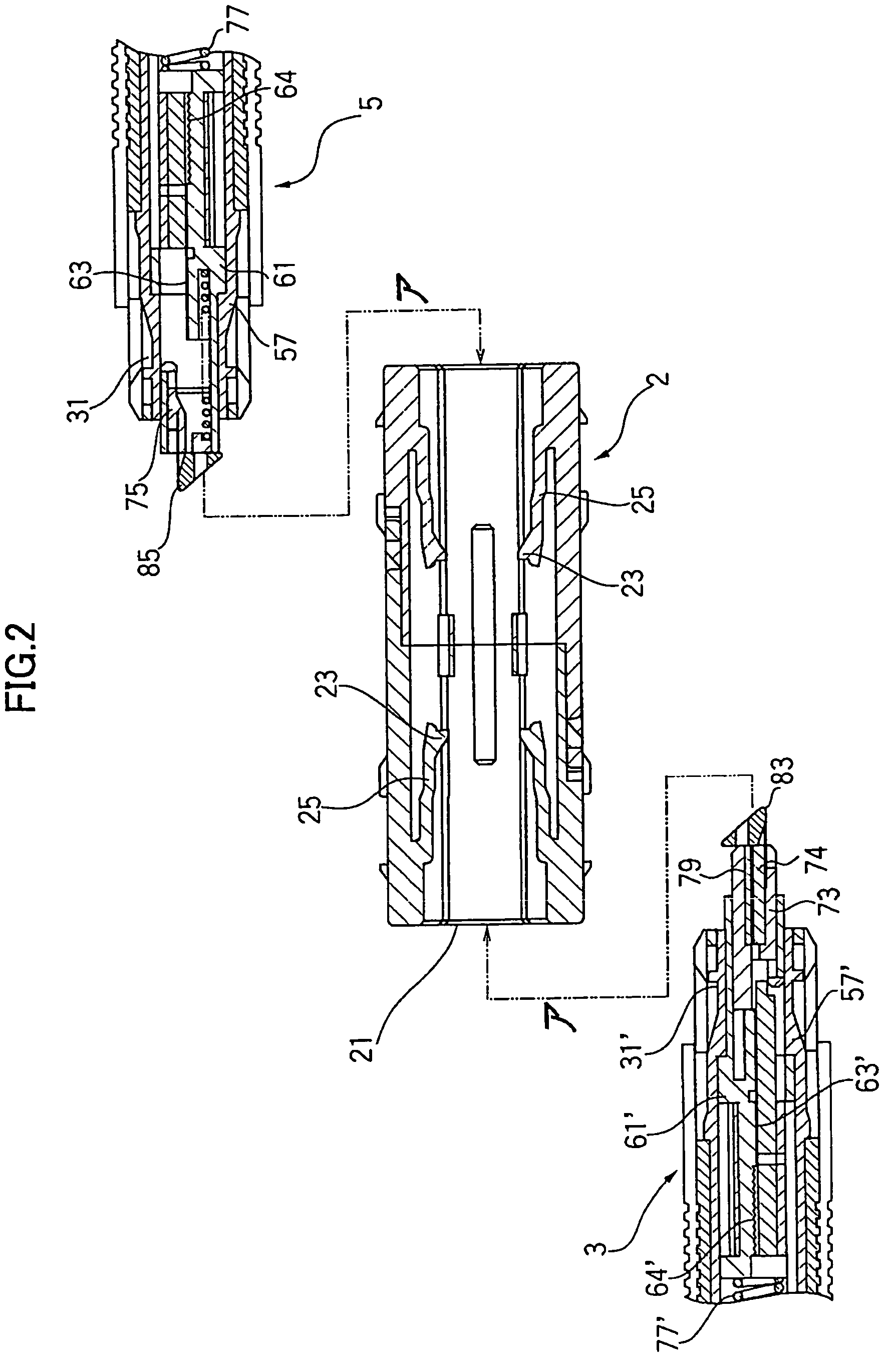
[0026]Hereinafter, an optical connector according to one embodiment of the present invention will be described.

[0027]In the present embodiment, an optical connector of a type wherein the “fiber wires (which are optical fibers without coating, while optical fibers with coating are fiber core wires)” of optical fibers are collided and connected with each other on their end faces will be particularly described. However, the present invention can be applied not only to the optical connector of the above type but also to an optical connector using fiber wires covered with zirconia or the like.

[0028]Further, in the present embodiment, a multicore optical connector, i.e. an optical connector comprising a plurality of optical fibers will be particularly illustrated as an example. However, as is obvious from the following description, the present invention can be applied not only to the multicore optical connector but also to a single-core optical connector comprising one optical fiber.

1. Ov...


PUM


Abstract

There is provided an optical connector device which prevents leakage of light until right before connectors are connected to each other and is small-sized by a reduction in space for housing shutters. The optical connector device is an optical connector device comprising a first optical connector and a second optical connector. When shutters for shutting out light from the optical connectors are collided with each other, the shutters move to positions where they do not shut out the light. Therefore, the first optical connector and the second optical connector are connected to each other. After moving, the shutter of the first optical connector and the shutter of the second optical connector are inserted into the second optical connector while remaining contacting each other.

Description

RELATED APPLICATION[0001]This application is a U.S. Continuation Application of International Application PCT / JP2004 / 012531 filed 31 Aug. 2004.BACKGROUND OF THE INVENTION[0002](i) Field of the Invention[0003]This invention relates to an optical connector having a shielding mechanism for preventing leakage of light from optical fibers.[0004](ii) Description of the Related Art[0005]For example, Japanese Patent Laid-Open Publication No. 526803 / 2001 discloses a conventional optical connector having a shielding mechanism. Two of such optical connectors are connected to each other via an adapter. The adapter has a shutter for preventing leakage of light from optical fibers of the two optical connectors, and each of the optical connectors also has a shutter. As for the shutter of the adapter, when the connectors are inserted into the adapter, the shutter is pushed upward in the adapter or moved to an opening position by the action of the inserted connectors. As for the shutters of the conn...

Claims


Application Information

Patent Timeline
Patent Type & Authority Patents(United States)
IPC IPC(8): G02B6/38G02B6/40
CPCG02B6/3825G02B6/3849G02B6/3885
Inventor TSUCHIDA, MASAHIROABE, YOSHITERUKOBAYASHI, MASARUNAGASE, RYOARISHIMA, KOICHIKOREEDA, YUICHIONOGAWA, AKIHIRO
Owner HIROSE ELECTRIC GROUP
Why Eureka
Try Eureka