Method and apparatus for machining a blank from all directions in a machine tool or milling machine

a technology of machine tools and milling machines, which is applied in the direction of mechanical equipment, manufacturing tools, turbines, etc., can solve the problems of inadequate and achieve the effects of improving the mounting of the workpiece, reducing the damage to the workpiece, and improving the quality of the final workpi

Inactive Publication Date: 2007-08-28
ALSTOM TECH LTD
View PDF27 Cites 37 Cited by
  • Summary
  • Abstract
  • Description
  • Claims
  • Application Information

AI Technical Summary

Benefits of technology

[0009]The reduction in setups and the use of only one machine tool or milling machine leads to a considerable simplification in the production process and to cost savings (less downtime, fewer means for the transfer of components, fewer milling machines, etc.) and nonetheless permits the production of final shapes which meet the highest quality requirements. The direct transfer from the adapter for the first machining step to the special gripping adapter for the second machining step without the use of a robot permits, in an especially simple, defined manner, the transfer from one setup to the next, which leads to a reduction in the requisite adjustments. In this context, “defined manner” means that the means for removing the partly machined workpiece, i.e. the special gripping adapters, grip this workpiece at a well-defined location, so that the partly machined workpiece can then be finish-machined in a likewise well-defined position in the second machining step. The effective configuration of the special gripping adapter (spacing and type of mounting points) therefore depends as a rule on the contour of the partly machined region of the workpiece.
[0020]As already mentioned at the beginning, the present invention also relates to a machine tool or milling machine for carrying out the method as described above. This machine tool or milling machine is characterized in that it has a milling spindle which is displaceable in three spatial directions and with which the workpiece can be machined in a machining region, in that the machine tool or milling machine has at least one mounting slide, with which the workpiece, for the first machining step, can be mounted in gripping adapters, and in that, furthermore, the machine tool or milling machine has at least one rocker, with which the partly machined workpiece can be mounted by means of at least one special gripping adapter in the first, finally machined region of the workpiece for the second machining step. In this case, the milling spindle is advantageously arranged on the one side of the mounting slides, whereas the rocker is advantageously arranged on the other side of the mounting slides. Thus, the at least one mounting slide, during the machining with mounting in the rocker in the second machining step, can be moved in a simple manner out of the machining region of the milling spindle.

Problems solved by technology

Normally, it has always been assumed that the forces produced during the machining lead either to damage to the workpiece or to inadequate quality of the final workpiece (e.g. as a result of vibrations, moments, etc.).

Method used


Image

  • Method and apparatus for machining a blank from all directions in a machine tool or milling machine
  • Method and apparatus for machining a blank from all directions in a machine tool or milling machine
  • Method and apparatus for machining a blank from all directions in a machine tool or milling machine

Examples


Embodiment Construction

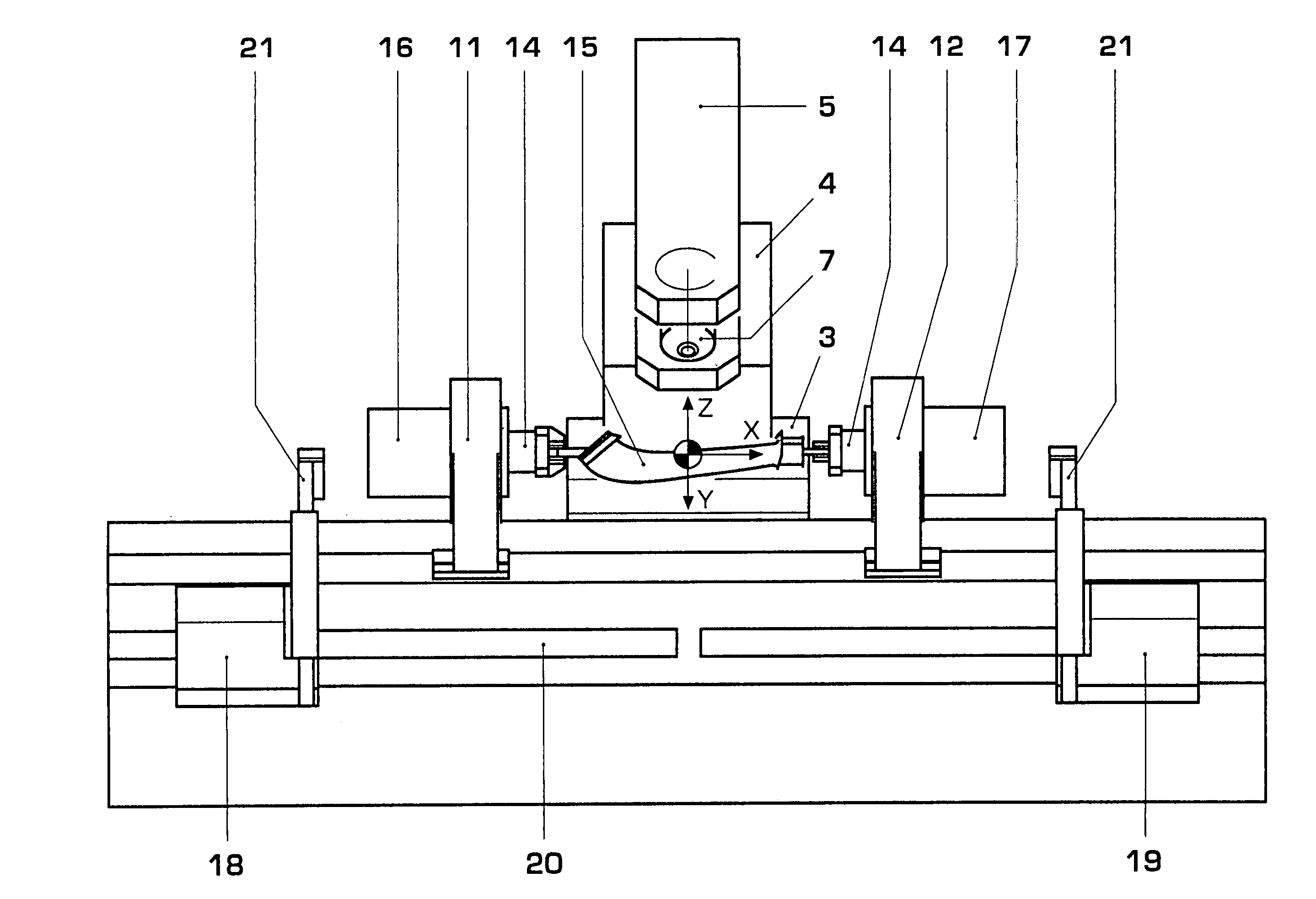
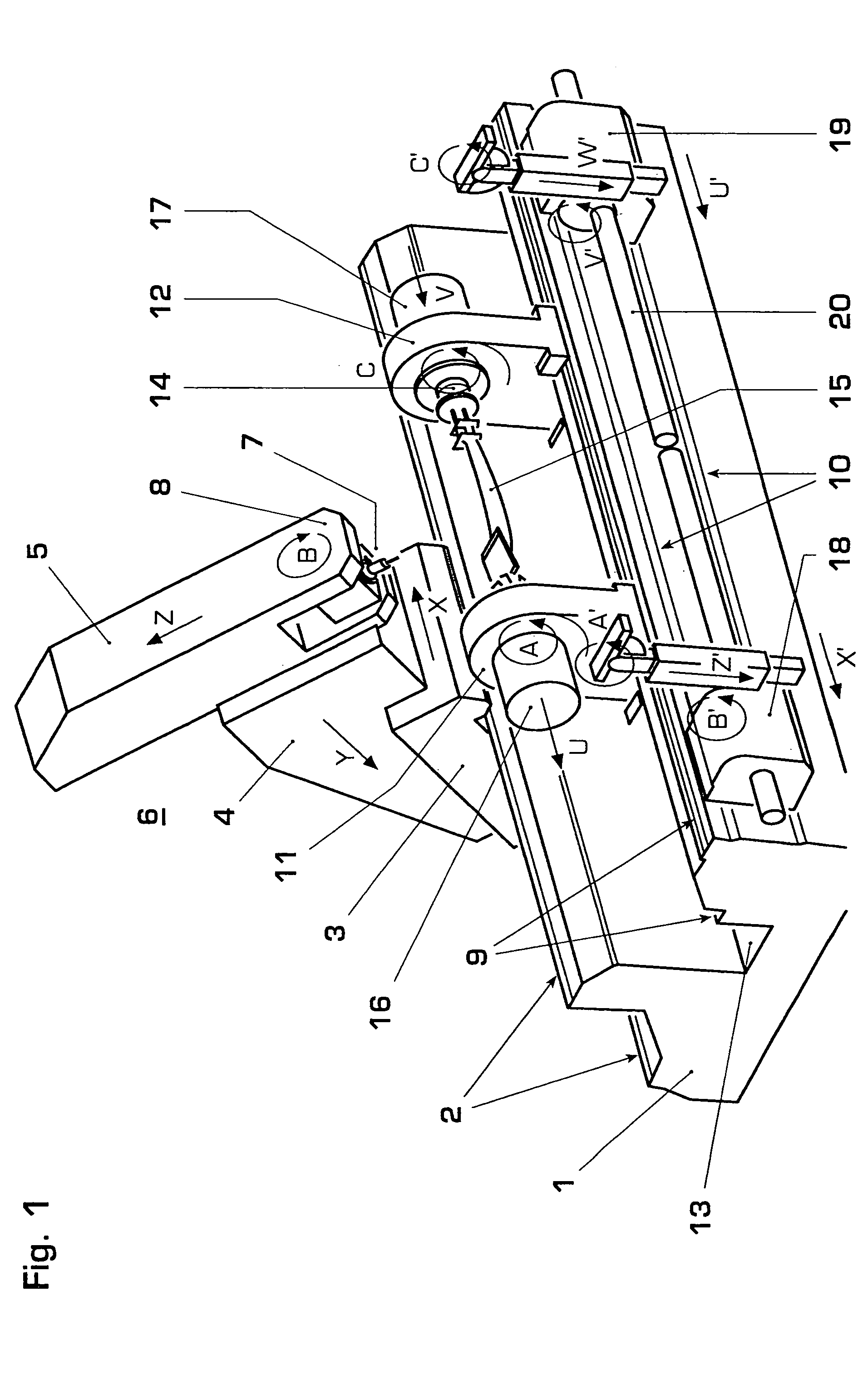
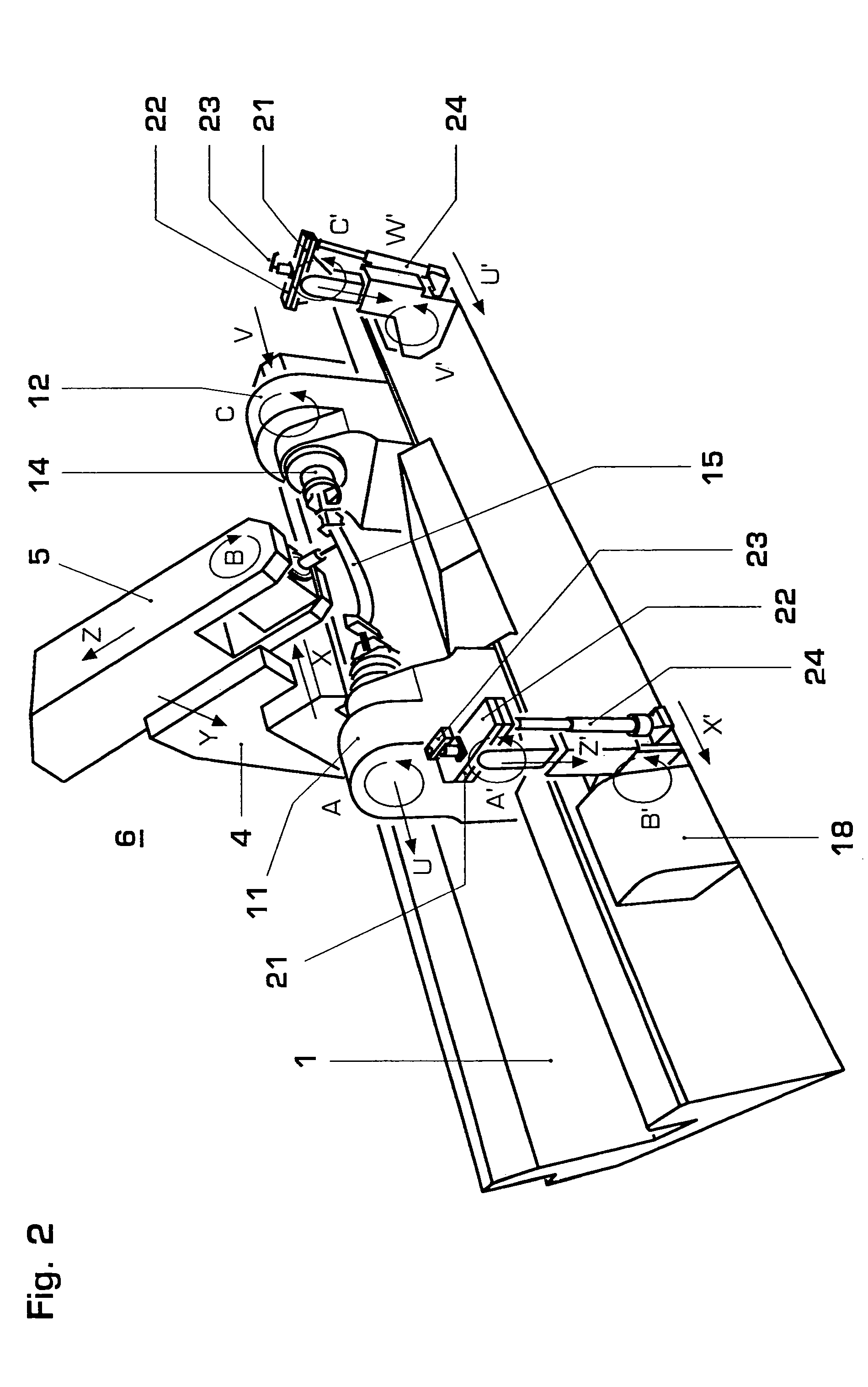
[0034]FIGS. 1 and 2 show a blade milling machine in perspective view. The milling machine has a base frame 1 on which the individual elements are mounted. The two guideways 2 for the base slide unit 3 of the UNI milling spindle 7 are provided at a defined angle on the rear side of the base frame 1. The two guideways 9 for the A-axis slides 11 and 12 are provided in the center region. The guideways 10 for the two rockers 21 are provided at the front. The chip passage 13 is integrated between the guideways 2 and 9. The chip passage 13 has been transversely ribbed in order to ensure that the frame is not weakened. The Y slide unit 4 of the UNI milling spindle 7, with which the Y stroke (Y) of the spindle is carried out, is mounted on the base slide unit 3 of the UNI milling spindle 7, which carries out the X stroke (X) of the spindle. The Z ram 5 is mounted on the Y slide 4 at an angle of 90 degrees to the Y stroke. The spindle carries out the Z stroke (Z) by means of said Z ram 5. The...


PUM

PropertyMeasurementUnit
weightaaaaaaaaaa
diameteraaaaaaaaaa
lengthaaaaaaaaaa

Abstract

The corresponding machine tool or milling machine for carrying out the method described has a milling spindle which is displaceable in three spatial directions and with which the workpiece can be machined in a machining region, the machine tool or milling machine having at least one mounting slide, with which the workpiece, for the first machining step, can be mounted in gripping adapters. Furthermore, the machine tool or milling machine has at least one rocker, with which the partly machined workpiece can be mounted by means of at least one special gripping adapter in the first, finally machined region of the workpiece for the second machining step.

Description

CROSS-REFERENCE TO RELATED APPLICATIONS[0001]This application is a continuation of the U.S. National Stage designation of co-pending International Patent Application PCT / CH03 / 00059 filed Jan. 24, 2003, the entire content of which is expressly incorporated herein by reference thereto.FIELD OF THE INVENTION[0002]The present invention relates to a method of machining blanks or pre-machined workpieces from all directions using a machine tool, such as a milling machine for example, to produce components that are finally machined in their three-dimensional shape and to a machine tool, such as a milling machine for example, for carrying out such a method.BACKGROUND OF THE INVENTION[0003]During the production of turbine blades, work is normally carried out with multi-spindle machining. This means that a blank is first of all subjected to rough pre-machining, then the airfoil region is processed in detail, and then the tip and finally the root are produced. Between these individual machining...

Claims


Application Information

Patent Timeline
Patent Type & Authority Patents(United States)
IPC IPC(8): B23C3/18B23P15/02B23Q3/02
CPCB23C3/18B23B2215/81Y10T409/309968Y10T409/309016Y10T409/307448Y10T29/49336Y10T409/303808Y10T29/5114Y10T409/30756Y10T409/305544
Inventor KILLER, FRANZSCHERER, JOSEF
Owner ALSTOM TECH LTD
Why Eureka
Try Eureka