Poultry wing separator and partial deboner

a technology of poultry wings and separators, applied in the field of poultry wing separators and deboning systems, can solve the problems of difficult eat of wings, limited use of poultry wings, and less economical use of poultry wings, and achieve the effect of reducing the residue of greas

Inactive Publication Date: 2007-08-28
SYSTATE GROUP
View PDF24 Cites 29 Cited by
  • Summary
  • Abstract
  • Description
  • Claims
  • Application Information

AI Technical Summary

Benefits of technology

[0007]Briefly described, the present invention concerns a method and apparatus for separating the segments of poultry wings from one another and deboning an end of the bones of the segments, leaving the end portions of the bones exposed. The products are later cooked so as to evaporate or otherwise diminish the residue of grease, etc. on the exposed bone ends, making them more suitable for grasping by the person that consumes the meat from the bone.

Problems solved by technology

The use of poultry wings is somewhat limited because the amount of meat in the wing segments is relatively small when compared to other parts of the poultry carcass, and because the wing segments contain bones that are difficult to remove.
This causes the use of poultry wings to be less economical than the use of other available poultry parts and parts of other carcasses.
While this use of poultry wings and wing segments is economical because the products do not have to be deboned before consumption, the wings are somewhat difficult to eat, particularly because the person eating the wings must grasp the wing with his or her hands, leaving a residue of grease or other undesirable matter on the hands.
Also, during the cooking process, the meat usually shrinks and moves away from the exposed bone end, increasing the amount of exposed bone.
However, the hand operations were expensive and, therefore, the process was not economical.
However, the small size of the poultry wings and wing segments causes the process of producing the product to become cumbersome, unreliable, and uneconomical.

Method used


Image

  • Poultry wing separator and partial deboner
  • Poultry wing separator and partial deboner
  • Poultry wing separator and partial deboner

Examples


Embodiment Construction

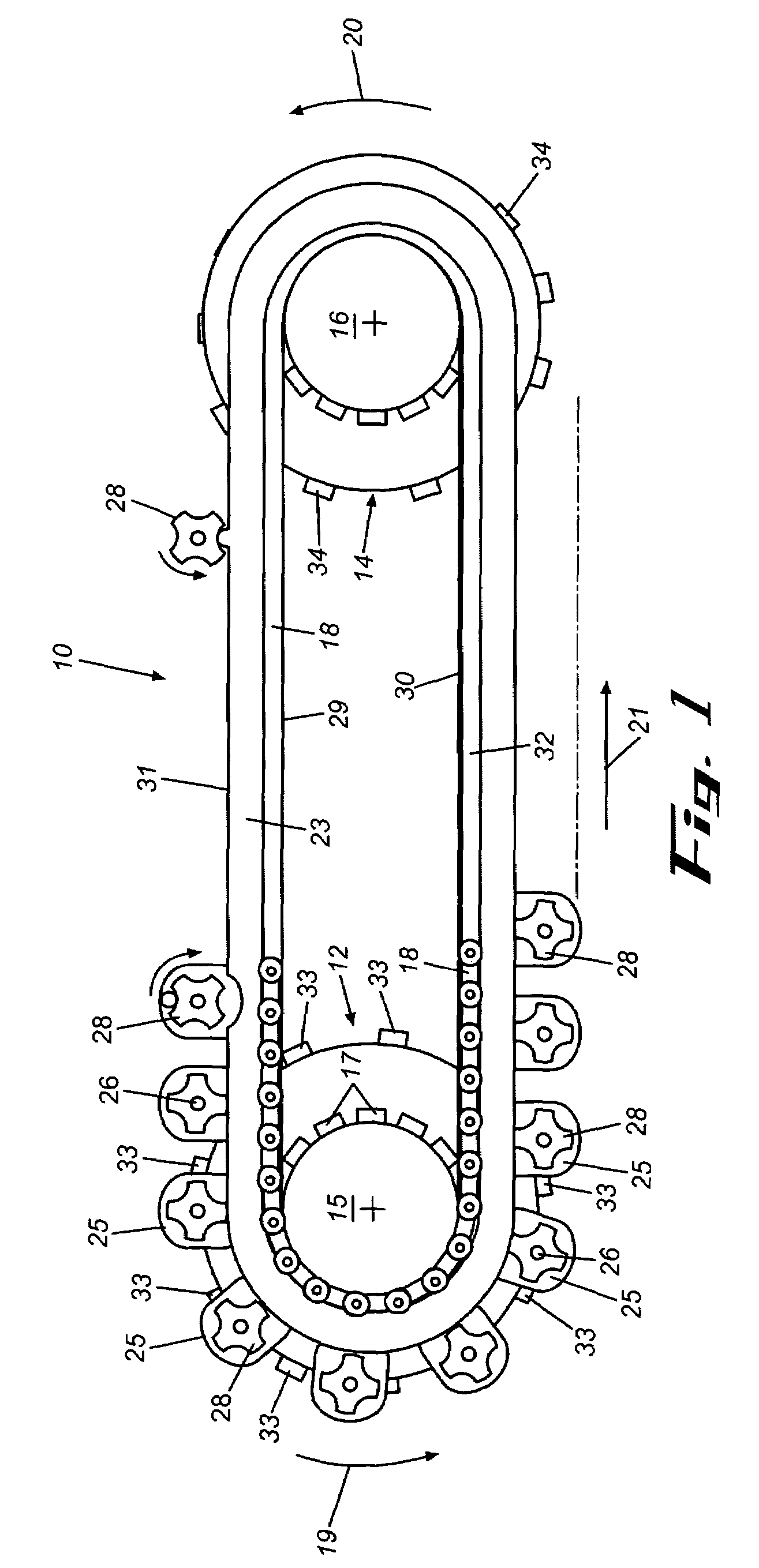
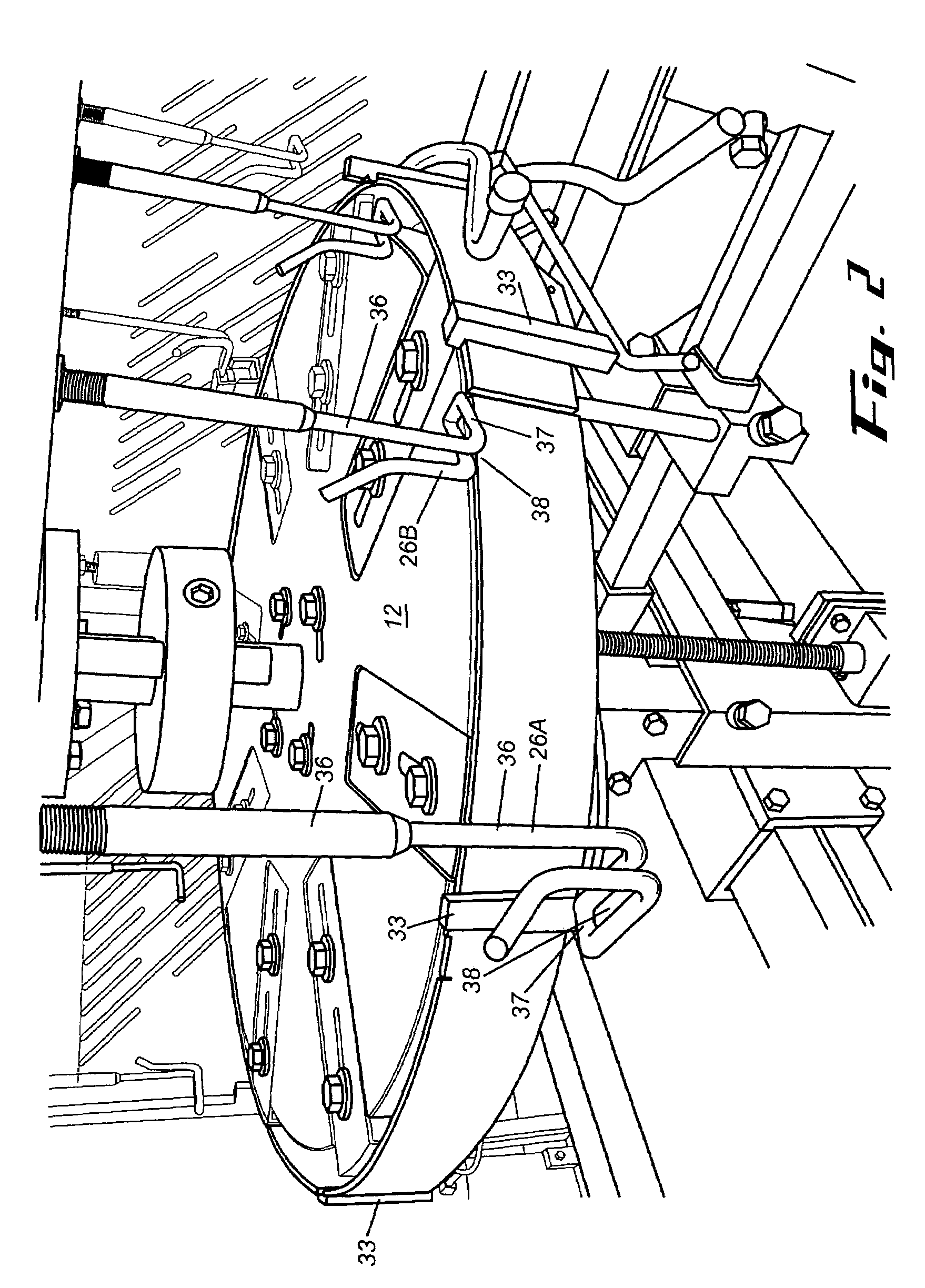
[0029]Referring now in more detail to the drawings, in which like numerals indicate like parts throughout the several views, FIG. 1 illustrates the top of the poultry wing separator and partial deboner 10, showing the drive system for moving the shackles in series along the processing path.

[0030]Primary segment rotary guide 12 is operatively connected to the mid-wing segment rotary guide 14 by drive gear 15, driven gear 16, the teeth 17 of the gears, and continuous drive chain 18. The teeth 17 of the drive gear and driven gear mesh with the chain, and a motor or other source of power (not shown) is connected to drive gear to impart rotary movement to the drive gear, drive chain and driven gear as indicated by direction arrows 19, 20 and 21 about upright axes 22A and 22B.

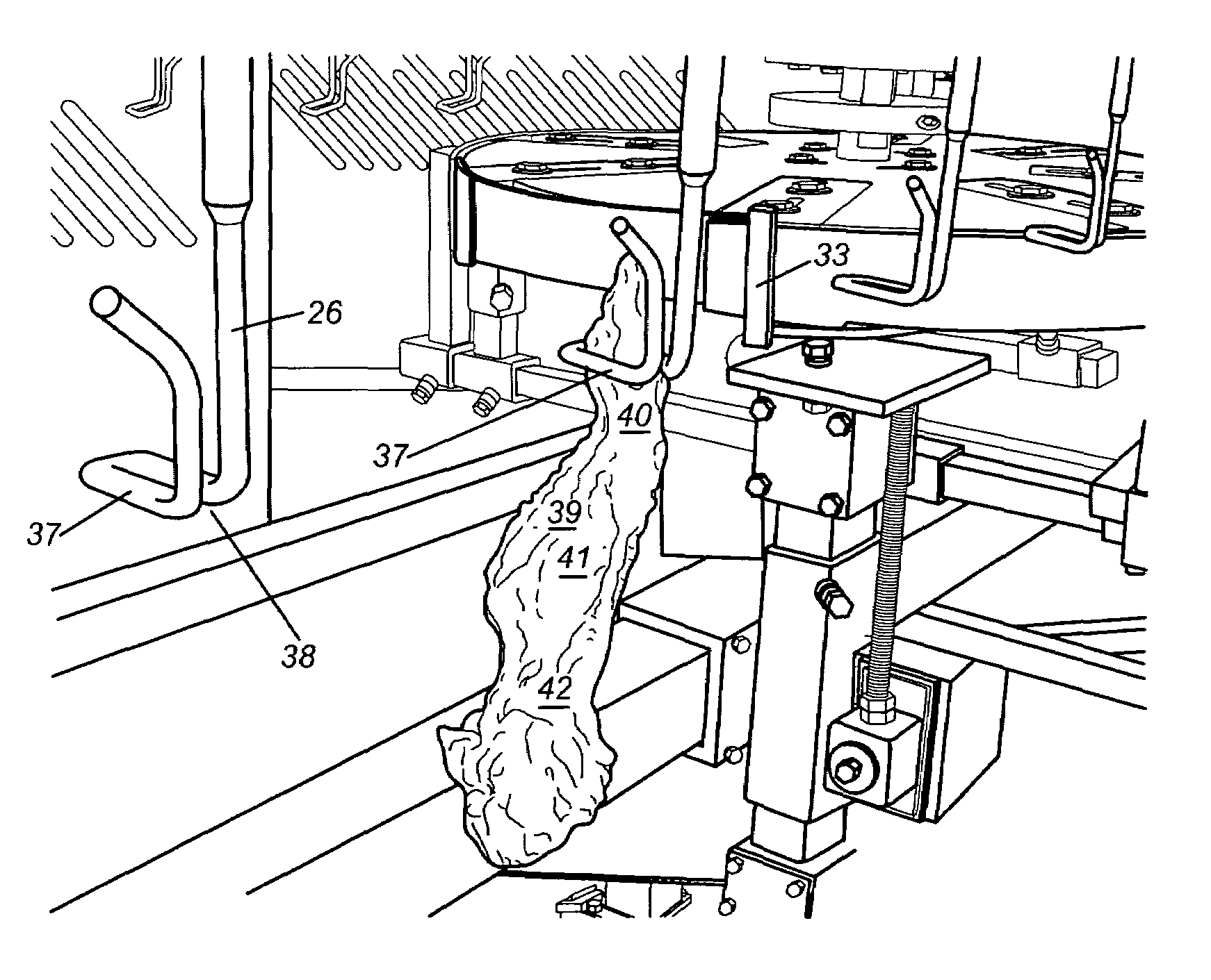
[0031]The drive chain 18 is driven adjacent a cam track 23 that extends about the drive and driven gears 15 and 16, and shackle supports 25 are carried at spaced intervals by the drive chain and project on the opposi...


PUM


Abstract

Poultry wings are suspended by their tip segments and oriented so that their outside surfaces face one side of the processing path, with right wings oriented with their elbows leading, and left wings oriented with their elbows trailing. The lower, primary segments are bent at the elbow joints by a bending guide, laterally and upwardly about an elbow guide, opening the elbow joints. The open joints are cut so as to release the primary segments. The mid-wing segments are compressed and the bone ends are moved laterally from the wing tip segments, causing the bone ends of the mid-wing segments to pop out of the tip segments. In both instances, the bones of the segments are exposed in the final products, so when the products are cooked, the exposed bone ends are free of grease, etc. and are suitable for grasping by the fingers of the hand for eating as finger food.

Description

FIELD OF THE INVENTION[0001]This invention concerns a poultry wing segment separator and deboning system for separating segments of the wings of poultry carcasses, and for deboning an end portion of the segments, leaving the end portions of the bones of the segments exposed.BACKGROUND OF THE INVENTION[0002]The use of poultry wings is somewhat limited because the amount of meat in the wing segments is relatively small when compared to other parts of the poultry carcass, and because the wing segments contain bones that are difficult to remove. This causes the use of poultry wings to be less economical than the use of other available poultry parts and parts of other carcasses.[0003]Because of these problems, poultry wings and wing segments have been eaten by holding the cooked wings or wing segments in the hands and eating the meat away from the bones. While this use of poultry wings and wing segments is economical because the products do not have to be deboned before consumption, the ...

Claims


Application Information

Patent Timeline
Patent Type & Authority Patents(United States)
IPC IPC(8): A22C17/02A22C17/00A22C21/00
CPCA22C21/0023A22C21/0084
Inventor HOLLEMAN, LEEN
Owner SYSTATE GROUP
Why Eureka
Try Eureka