Exposure apparatus and exposure method for performing high-speed and efficient direct exposure

a technology of direct exposure and exposure apparatus, which is applied in the direction of instruments, printers, therapy, etc., can solve the problems of increasing the cost of light sources, the inability to expose the photoresist, etc., and achieve the effect of speeding up the direct exposure process, reducing the number of exposure engines, and reducing the cost of exposure engines

Active Publication Date: 2007-08-28
SHINKO ELECTRIC IND CO LTD
View PDF9 Cites 13 Cited by
  • Summary
  • Abstract
  • Description
  • Claims
  • Application Information

AI Technical Summary

Benefits of technology

[0039]To achieve the above object, in the present invention, the plurality of exposure devices in each exposure engine are first divided into groups. Each group thus formed is called the “exposure device group”. The exposure device groups are formed by dividing the plurality of exposure devices arranged in a two-dimensional array into groups along a direction perpendicular to the direction of relative movement of the exposure target substrate. In this case, if one looks at the n-row, m-column bitmap data to be used for direct exposure, it is seen that, according to the present invention, the number, n, of rows in the bitmap data can be reduced compared with the bitmap data before dividing the two-dimensional array of exposure devices into groups. As a result, if there is an upper limit value on the bandwidth that defines the capacity of data transmission between the exposure engine and the memory device in which the bitmap data is stored, the frame rate f can be further increased, and thus the speedup of the direct exposure process can be achieved. Furthermore, since the number, m, of columns in the bitmap data can also be increased, the number of exposure engines can be reduced, achieving a reduction in the cost of the exposure engines, while also making it possible to handle a larger amount of bitmap data.

Problems solved by technology

However, the amount of light energy that each one of the exposure device groups can project onto the exposure target substrate moving relative to the exposure engine is smaller than the amount of light energy that the conventional exposure engine not divided into groups projects.
If this light energy does not exceed the threshold for exposing the photoresist applied on the exposure target substrate, the exposure of the photoresist cannot be accomplished.
One possible method to compensate for such reduction in the light energy would be to increase the light energy of the light source, but this would not be desirable as it would lead to an increase in the cost of the light source.

Method used


Image

  • Exposure apparatus and exposure method for performing high-speed and efficient direct exposure
  • Exposure apparatus and exposure method for performing high-speed and efficient direct exposure
  • Exposure apparatus and exposure method for performing high-speed and efficient direct exposure

Examples


Embodiment Construction

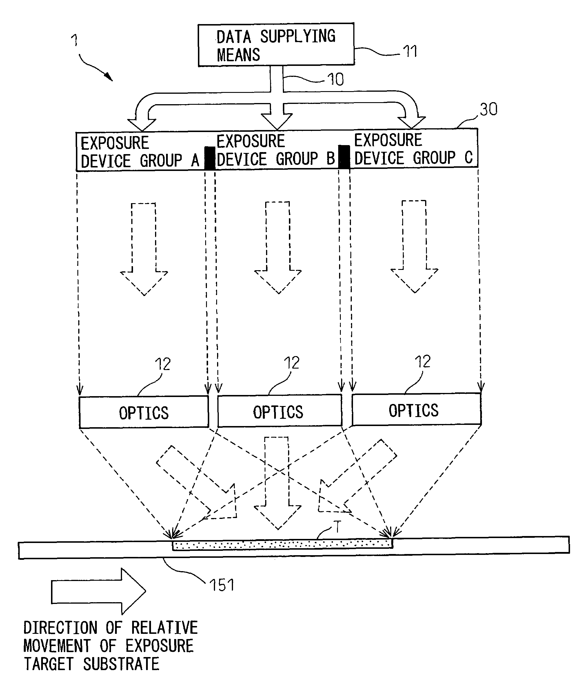
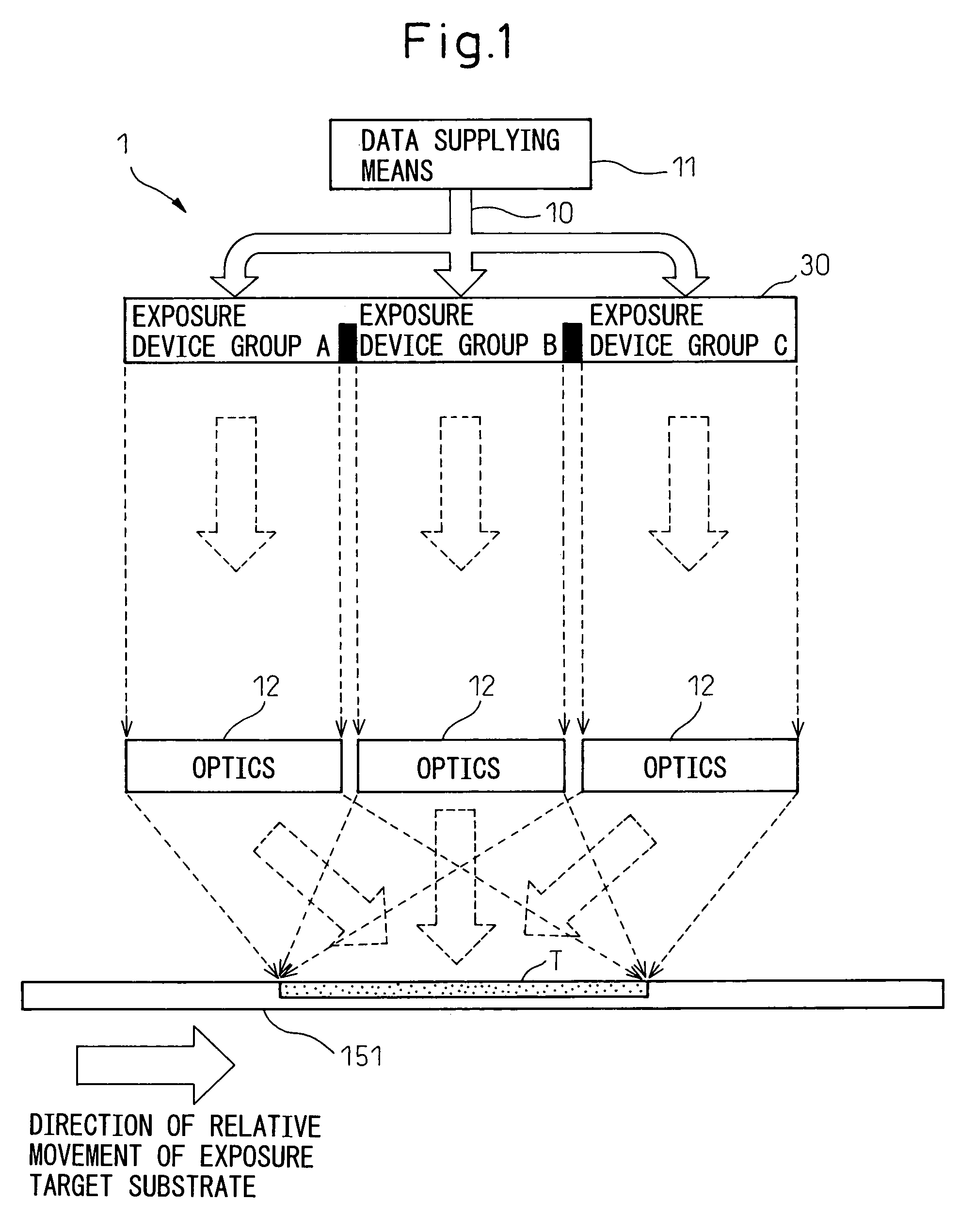
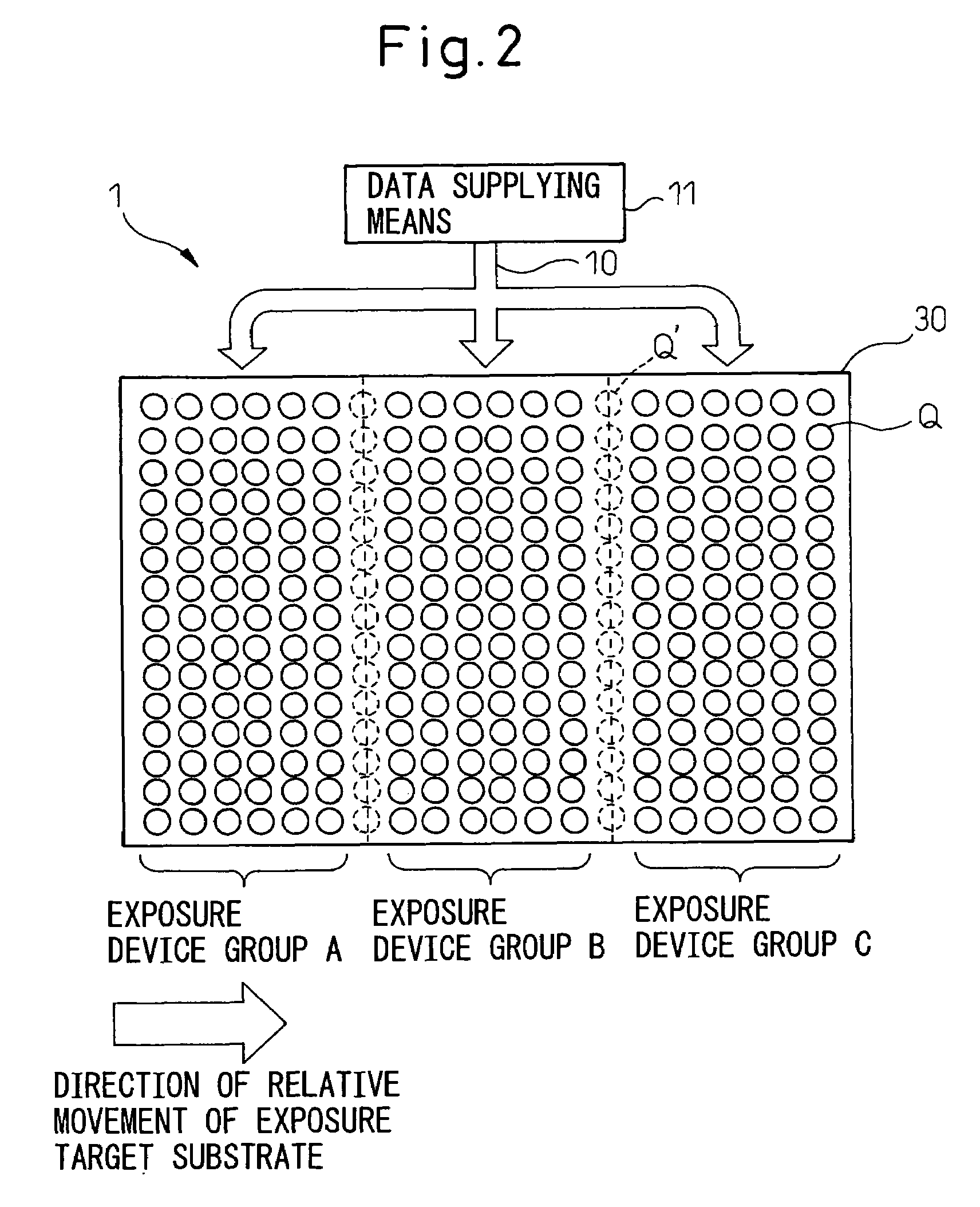
[0068]The greatest feature of the exposure apparatus of the present invention is that the plurality of exposure devices in each exposure engine are divided into a plurality of exposure device groups, and that the lights produced from the respective exposure device groups based on the same exposure data are projected via optics so as to be superimposed one on top of another on the same area on the exposure target substrate.

[0069]In the embodiment of the present invention, the “same exposure data” to be supplied to the respective device groups is generated by using the exposure data generated for one particular exposure device group and duplicating the same for the other exposure device groups. Generally, a very large amount of computation is required to generate exposure data but, by duplicating the data as just described, the amount of computation can be reduced, which offers a significant effect of being able to enhance the speed of the entire processing.

[0070]FIG. 4 is a diagram s...


PUM


Abstract

In an exposure apparatus, in which exposure data necessary for direct exposure is sequentially supplied to an exposure engine having a plurality of exposure devices and, based on the supplied exposure data, the exposure engine forms an exposure pattern on an exposure target substrate which moves relative to the exposure engine, lights respectively produced from the exposure device groups based on the identical exposure data supplied to each of the plurality of exposure device groups, are projected via optics so as to be superimposed one on top of another on the same area on the exposure target substrate.

Description

BACKGROUND OF THE INVENTION[0001]1. Filed of the Invention[0002]The present invention relates to an exposure apparatus and an exposure method for directly exposing an exposure target substrate, and more particularly to an exposure apparatus and an exposure method in which exposure data necessary for direct exposure is sequentially supplied to an exposure engine having a plurality of exposure devices and, based on the thus supplied exposure data, the exposure engine forms an exposure pattern on an exposure target object, for example, an exposure target substrate moving relative to the exposure engine.[0003]2. Description of the Related Art[0004]Generally, a wiring pattern on a wiring substrate is formed by applying a photoresist over the substrate, exposing the photoresist based on wiring pattern design data, and developing and printing the desired pattern on the substrate, followed by etching. In the exposure process, a photomask is usually used.[0005]On the other hand, a patterning...

Claims


Application Information

Patent Timeline
Patent Type & Authority Patents(United States)
IPC IPC(8): G03B27/54G03B27/42
CPCG03F7/70283G03F7/70291G03F7/70508
Inventor SEKIGAWA, KAZUNARI
Owner SHINKO ELECTRIC IND CO LTD
Why Eureka
Try Eureka