Apparatus and method for synchronizing symbol timing using timing loop controller

a timing loop controller and symbol technology, applied in the field of symbol timing synchronizer, can solve the problems of increasing the timing zitter and the time error finally being computed, and achieve the effect of eliminating the noise of the timing error valu

Inactive Publication Date: 2007-08-28
ELECTRONICS & TELECOMM RES INST
View PDF13 Cites 7 Cited by
  • Summary
  • Abstract
  • Description
  • Claims
  • Application Information

AI Technical Summary

Benefits of technology

[0011]It is, therefore, an object of the present invention to provide a symbol timing synchronizer using a timing synchronous loop controller for multilevel modulation scheme in order to overcome a characteristic of high order modulation method having irregular shift of zero crossing and its multilevel input signal, and in order to reduce dispersion value of timing errors according to a signal-to-noise ratio and a zitter value when detecting, a method thereof and a computer readable recoding medium storing a program for executing the same method.
[0012]It is another object of the present invention to provide a method and computer readable recoding medium storing a program for executing the same method, where in the method for multilevel modulation scheme in order to overcome a characteristic of high order modulation method having irregular shift of zero crossing and its multilevel input signal, and in order to reduce dispersion value of timing errors according to a signal-to-noise ratio and a zitter value when detecting.
[0014]In accordance with another aspect of the present invention, there is also provided a symbol timing synchronizer using a timing synchronous loop controller for multilevel modulation scheme, including: a A / D conversion unit for converting successively inputted analogue signals to digital signals; a timing error detection unit for calculating an timing error between an input timing of the digital signal successively inputted from the A / D conversion unit and a sampling timing of the A / D conversion unit and detecting sign change of the digital signals; a timing error output control unit for outputting the timing error calculated from the timing error detection unit and controlling the timing error output value; a filtering unit for eliminating a noise of the timing error value controlled by the timing error output control unit and calculating a mean value of errors; and a timing error compensation unit for compensating the timing error of the sampling timing of the A / D conversion unit by shifting the sampling timing corresponding to the calculated error value from the timing error detection unit.
[0015]In accordance with still another aspect of the present invention, there is also provided a method for synchronizing symbol timing by using a timing synchronous loop controller, the method including the steps of: a) converting successively inputted analogue signals to digital signals by an A / D conversion unit; b) calculating an timing error between an input timing of the digital signal successively inputted from the A / D conversion unit and a sampling timing of the A / D conversion unit and detecting sign change of the digital signals by a timing error detection unit; c) outputting the timing error calculated from the timing error detection unit and controlling the timing error output value; d) eliminating a noise of the timing error value and calculating a mean value of errors; and e) compensating the timing error of the sampling timing of the A / D conversion unit by shifting the sampling timing corresponding to the calculated error value from the timing error detection unit.
[0016]In accordance with further still another aspect of the present invention, there is also provided a computer readable recoding medium for storing instructions for executing a method for synchronizing a symbol timing by using a timing synchronous loop controller, the method including the steps of: a) converting successively inputted analogue signals to digital signals by an A / D conversion unit; b) calculating an timing error between an input timing of the digital signal successively inputted from the A / D conversion unit and a sampling timing of the A / D conversion unit and detecting sign change of the digital signals by a timing error detection unit; c) outputting the timing error calculated from the timing error detection unit and controlling the timing error output value; d) eliminating a noise of the timing error value and calculating a mean value of errors; and e) compensating the timing error of the sampling timing of the A / D conversion unit by shifting the sampling timing corresponding to the calculated error value from the timing error detection unit.

Problems solved by technology

Therefore, a timing error finally is computed by using the multipliers and the adders.
However, the conventional timing error detector can calculate the timing error when the multilevel signals are not crossed at ‘0’ point since the conventional timing error detector detects the timing error at every sample clock by using two digital signal per one symbol, which is inputted in order.
It causes to increase a timing zitter since the conventional timing error detector may calculate a value not near to ‘0’ point as the timing error.

Method used


Image

  • Apparatus and method for synchronizing symbol timing using timing loop controller
  • Apparatus and method for synchronizing symbol timing using timing loop controller
  • Apparatus and method for synchronizing symbol timing using timing loop controller

Examples


Embodiment Construction

[0026]Other objects and aspects of the invention will become apparent from the following description of the embodiments with reference to the accompanying drawings, which is set forth hereinafter.

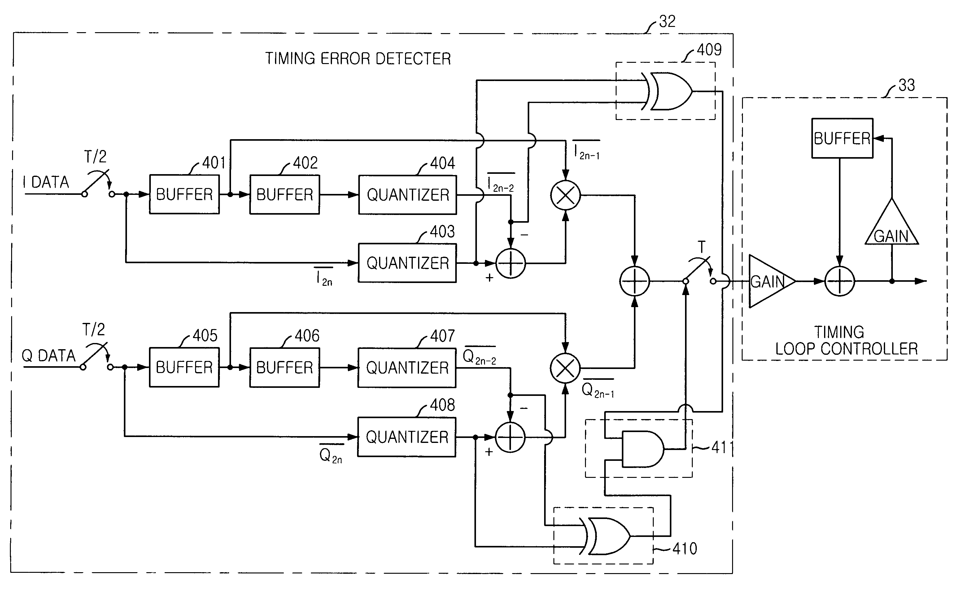
[0027]FIG. 3 is a diagram illustrating a symbol timing synchronizer using a timing loop controller in accordance with a preferred embodiment of the present invention.

[0028]Referring to FIG. 3, the symbol timing synchronizer using the timing loop controller includes an analog / digital (A / D) converter 31 for converting successively inputted analogue signals to digital signals; a timing error detector 32 for calculating a timing error between the digital signal orderly inputted from the A / D converter and a sampling timing of the A / D converter 31 and detecting variation of sign of the digital signal; a timing error output controller 33 for outputting the timing error calculated from the timing error detector 32 and controlling the timing error output value; a low pass filter 34 for eliminating a...


PUM


Abstract

A timing loop controller for multilevel modulation scheme is disclosed. The timing loop controller includes a first to fourth computing unit for computing a timing error between an input timing of digital signals and a sampling timing; a first to fourth quantization unit for controlling a direction and an error value of the timing error; a first and second sign detection unit for detecting sign change according to results; a zero crossing detection unit for detecting zero crossing at I axis and Q axis; and a timing error control unit for controlling the timing error value in case there is no sign change. The present invention can increase a zitter performance of timing error according to the signal-to-noise ratio by detecting the timing error, outputting the timing error and controlling the timing error output value only in case there is sign change by additionally equipping the sign variation detector.

Description

FIELD OF THE INVENTION[0001]The present invention relates to a symbol timing synchronizer and a method thereof; and, more particularly, to a symbol timing synchronizer using a timing synchronous loop controller for multilevel modulation scheme in order to detect and compensate symbol timing error of multilevel signal, a method thereof, and a computer readable recoding medium storing a program for executing the same method.DESCRIPTION OF RELATED ART[0002]Generally, in order to detect and compensate exact symbol timing error of an input signal, Gardner method is widely used. Gardner method is disclosed by F. M. Gardner at “A BPSK / QPSK Timing-error Detector for sample data receivers,” IEEE Trans. Commun., vol. COM-34, pp. 423-429, May 1986.[0003]FIG. 1 is a circuit diagram showing a conventional timing fixed loop circuit. The conventional timing fixed loop circuit is a symbol timing synchronizer synchronizing a timing of the input signal and a sampling timing of a receiver.[0004]Referr...

Claims


Application Information

Patent Timeline
Patent Type & Authority Patents(United States)
IPC IPC(8): H04L27/06H04L7/00H04L7/02H04L7/033H04L25/34
CPCH04L7/0054H04L7/00
Inventor KIM, PANSOOKIM, YOUNG WANKIM, NAE-SOO
Owner ELECTRONICS & TELECOMM RES INST
Why Eureka
Try Eureka