Heat pump system

a heat pump and system technology, applied in the direction of refrigeration machines, heating apparatus, compression machines with reversible cycles, etc., can solve the problems of reducing affecting the efficiency of affecting the efficiency of the heat pump system. achieve the effect of reducing the heat transfer rate and maintaining the efficiency of the vapor compression system

Active Publication Date: 2007-09-04
MAHLE INT GMBH
View PDF19 Cites 10 Cited by
  • Summary
  • Abstract
  • Description
  • Claims
  • Application Information

AI Technical Summary

Benefits of technology

[0009]Accordingly, the subject invention provides a heat pump system having a heat exchanger that is operable as both an evaporator and a condenser. The heat exchanger includes a reduced heat transfer rate when operating as the evaporator to balance the heat transfer rate with a heat transfer rate of a condenser. Therefore, the heat pump of the present invention maintains the velocity of the refrigerant through the heat exchanger to maintain the efficiency of the vapor compression system in both the heating mode and the cooling mode.

Problems solved by technology

This results in an imbalance in the heat transfer rate between the evaporator and the condenser, undermining the system capacity and performance.
The lower velocity of the refrigerant circulating through the evaporator lowers the efficiency of the heat pump system.

Method used


Image

  • Heat pump system
  • Heat pump system
  • Heat pump system

Examples


Embodiment Construction

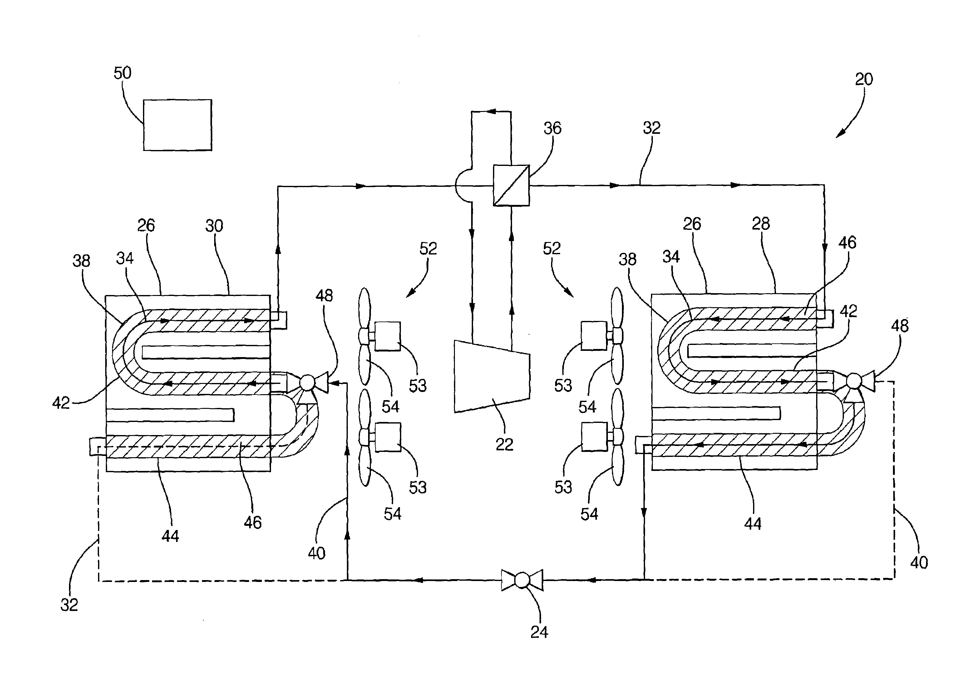
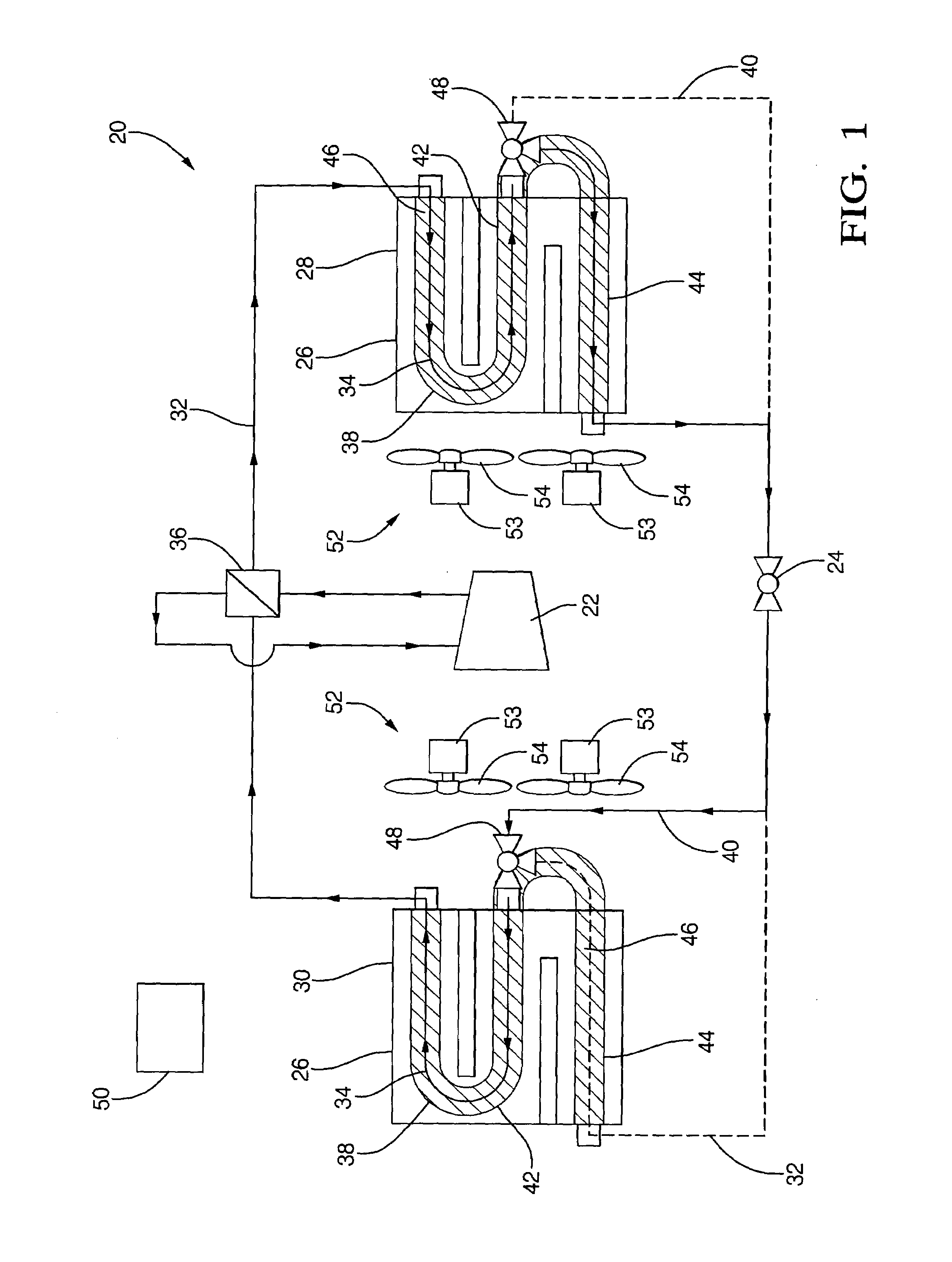
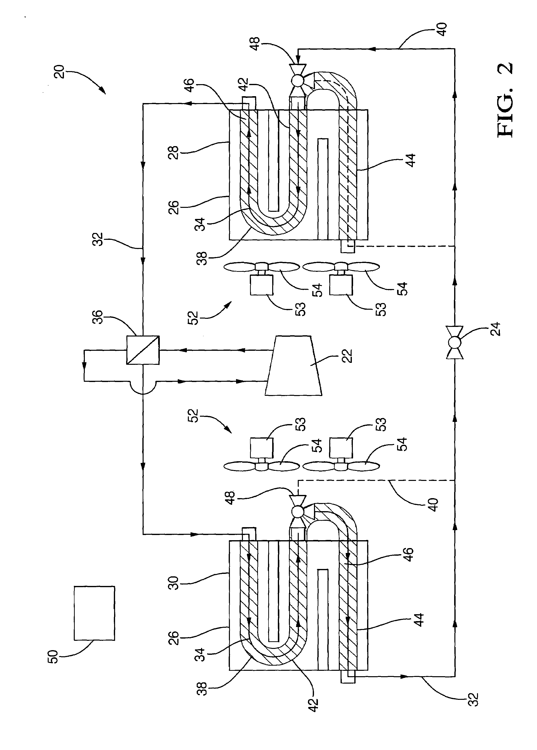
[0013]Referring to the Figures, wherein like numerals indicate corresponding parts throughout the several views, a heat pump system is shown generally at 20.

[0014]Referring to FIGS. 1 and 2, the heat pump system 20 is operable in a heating mode and a cooling mode and includes a compressor 22, an expansion device 24, and a heat exchanger 26. The heat exchanger 26 includes a first heat exchanger 28 and a second heat exchanger 30 with the first heat exchanger 28 operable as the evaporator in the cooling mode and the condenser in the heating mode and the second heat exchanger 30 operable as the condenser in the cooling mode and the evaporator in the heating mode.

[0015]A refrigerant circuit 32 interconnects the compressor 22, the expansion device 24, and the first and second heat exchangers 28, 30. A refrigerant 34 circulates through the refrigerant circuit 32, including the compressor 22, the expansion device 24, and the first and second heat exchangers 28, 30, in a direction.

[0016]The ...


PUM


Abstract

A heat pump is operable in a heating mode and a cooling mode and includes two identical heat exchangers. The heat exchangers alternate between operating as a condenser and an evaporator as the heat pump switches between the heating mode and the cooling mode. The heat exchangers include a fluid passageway for directing a refrigerant therethrough and a bypass bisecting the fluid passageway into a first portion and a second portion. A valve interconnects the first portion and the second portion of the fluid passageway and the bypass for directing the refrigerant through the first portion of the fluid passageway and into the bypass to prevent refrigerant flow through the second portion of the fluid passageway when the heat exchanger is operable as the evaporator.

Description

BACKGROUND OF THE INVENTION[0001]1. Field of the Invention[0002]The subject invention relates to a heat pump system operable in a heating mode and a cooling mode.[0003]2. Description of the Prior Art[0004]Heat pumps have been utilized to heat and cool structures for many years. The heat pump includes a vapor compression system including a compressor, a condenser, an evaporator, an expansion device, and a refrigerant circulating through the system. In addition to the vapor compression system, the heat pump includes a reversing valve for reversing the flow of the refrigerant within the system. The heat pump removes heat from within the structure when the refrigerant is circulating in a direction, and adds heat to the structure when the circulation of the refrigerant is reversed. The condenser and the evaporator are both heat exchangers, with the refrigerant dissipating heat in the condenser and the refrigerant absorbing heat in the evaporator. The condenser and the evaporator each inc...

Claims


Application Information

Patent Timeline
Patent Type & Authority Patents(United States)
IPC IPC(8): F25B13/00
CPCF25B13/00F25B2313/02321F25B2313/02523F25B2313/02741F25B2313/0293F25B2313/0294F25B2500/19
Inventor BHATTI, MOHINDER SINGH
Owner MAHLE INT GMBH
Why Eureka
Try Eureka