System and method for detecting leaks in pressurized piping systems

a technology of pressurized piping and leak detection, which is applied in the direction of fluid tightness measurement, pipe couplings, instruments, etc., can solve the problems of significant property damage and repair cost, mold and mold remediation, and loss of goodwill

Inactive Publication Date: 2007-09-04
ROBERT C RICHEY TRUSTEE OF THE ROBERT C RICHEY FAMILY TRUST
View PDF13 Cites 1 Cited by
  • Summary
  • Abstract
  • Description
  • Claims
  • Application Information

AI Technical Summary

Benefits of technology

[0008]It is an objective of this invention to provide both a leak detection system and method which enables plumbing system installers to ensure their plumbing systems are free of debris, excess flux and other residue, and whose joints do not contain any voids or other inadequacies which may give rise to a leak after the plumbing systems is enclosed.
[0009]Another objective of this invention is to provide a leak detection system and method which is both rugged and durable, as well as being both easy and relatively inexpensive to operate and maintain.
[0010]A still further object of this invention is to provide a leak detection system and method which allows for relatively quick plumbing system leak testing which affords a high degree of reliability.
[0011]The present invention comprises both a system and a method for identifying and eliminating debris and contamination in a new plumbing system and identifying one or more leaky plumbing system components from among a plurality of plumbing pipes and fittings. The present invention employs a water source, a conduit means for connecting the water source to the plumbing system, a pumping means for re-circulating the water through the plumbing system, a filtering means for cleansing and removing debris and contaminants from the plumbing system, a heating means for applying heat to the water source to elevate its temperature, a flow restriction means for isolating portions of the plumbing system, a pressure elevating means for increasing the pressure of the plumbing system, a means for measuring the plumbing system pressure and a pressure pulsating means for applying intermittent pressure surges to shock the plumbing system.

Problems solved by technology

Past history has shown that leaks caused by bad solder or glue joints cause significant property damage and cost of repairs, mold and mold remediation, insurance claims, loss of goodwill with the plumbing system purchaser and the plumbing system installer, and increased workloads and stress on plumbing installation service departments and operations.
In the context of new construction, major property damage and loss claims result when plumbing systems fail due to bad solder joints, glue joints, defective material, material damaged by others or faulty plumbing system installations after the plumbing systems have been covered with drywall or other wall coverings.
By way of background, current pressurized piping systems are often inadequately tested during their installation to determine whether any compromised pipe joints or piping components exist before they are placed into service.
Often, the piping system contains contaminants from the installation process which over time can cause problems with regard to leaks being exposed due to internal contamination and intermittent use.
Plumbing system contaminants can clog or foul plumbing fixtures over time if not removed from the plumbing system.
In the context of original home construction, plumbing systems are often left stagnant for periods of time prior to initial use and more often filled with debris.
However, after time and use, flux can be rinsed out of the system, giving rise to leaks often long after the original installation.
Also, repeated expansion and contraction of the plumbing system due to thermal expansion stresses can cause joint fatigue and often results in joint failure.
The prior art methods for testing plumbing systems suffer drawbacks in that they are individually inadequate to provide the level of test security for the plumbing system and, in most instances, are not employed in leak detection methods.

Method used


Image

  • System and method for detecting leaks in pressurized piping systems
  • System and method for detecting leaks in pressurized piping systems

Examples


Embodiment Construction

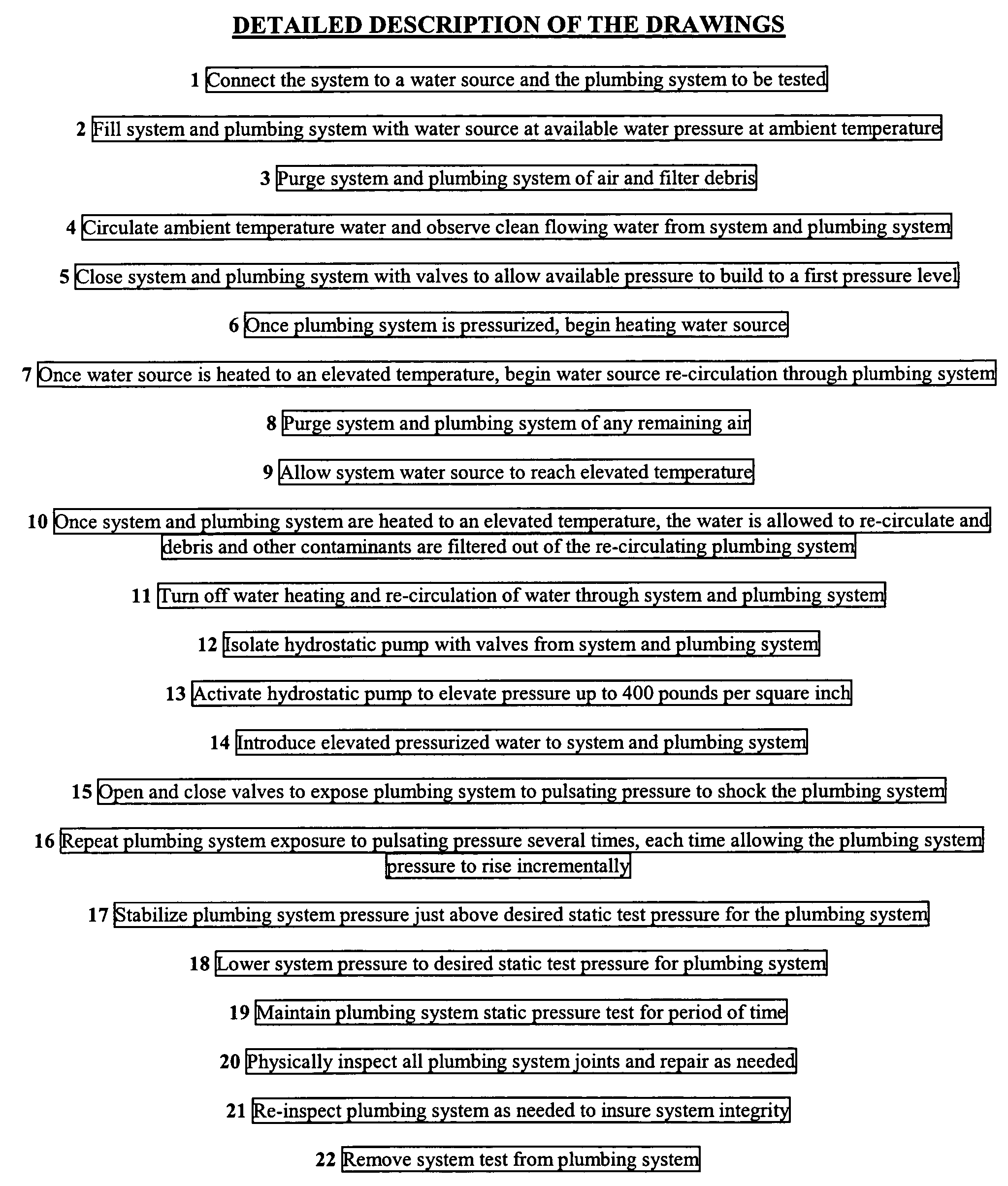
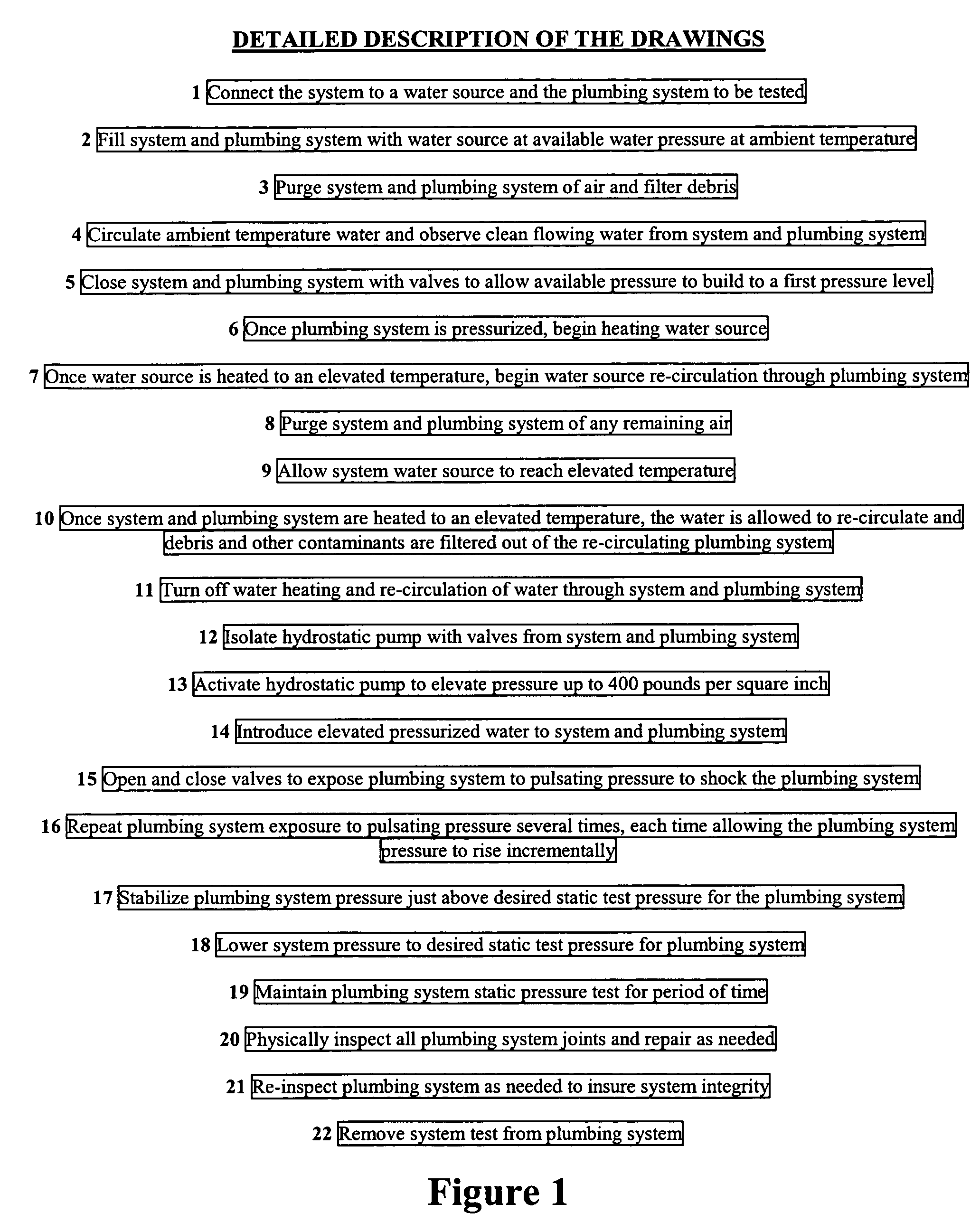
[0017]Referring now to FIG. 1, the method of the present invention is briefly described in a flow chart. The method begins by connecting the system and plumbing system to a water source (block 1). The system and plumbing system are then filled with the water source at available pressure (block 2). Air and debris are then filtered and purged from system and plumbing system (block 3). The system and plumbing system are observed until clean water is seen flowing through the system and plumbing system (block 4). The system and plumbing system are then closed with valves to allow available pressure to build in the system and plumbing system (block 5). Once the system and plumbing system are pressurized, the water source is heated to an elevated temperature (block 6). The elevated temperature water source is then re-circulated through the plumbing system to remove debris and contaminants from the plumbing system (block 7). Any remaining air in the closed plumbing system is then bled or pu...


PUM


Abstract

A system and method for testing plumbing systems for leaks by which the original plumbing system is cleaned and flushed using ambient temperature water followed by cleaning and flushing with pressurized recirculating elevated temperature water to filter debris and contaminants, shocking the plumbing system with elevated temperature and high pressure surges followed by a hydrostatic pressure test designed to expose the existence of any leaks in the plumbing system in the rough plumbing stage of construction prior to enclosing the plumbing system in a structure.

Description

BACKGROUND OF THE INVENTION[0001]The present invention generally relates to enhancing and improving current procedures for testing the integrity of newly installed water distribution systems for the purpose of preventing and eliminating water leaks caused by bad solder joints, bad glue joints, internal impurities or improper piping assembly. The present invention also relates to metal or plastic plumbing systems and may be used in domestic plumbing systems and commercial plumbing applications including fire sprinkler applications.[0002]Past history has shown that leaks caused by bad solder or glue joints cause significant property damage and cost of repairs, mold and mold remediation, insurance claims, loss of goodwill with the plumbing system purchaser and the plumbing system installer, and increased workloads and stress on plumbing installation service departments and operations. In the context of new construction, major property damage and loss claims result when plumbing systems...

Claims


Application Information

Patent Timeline
Patent Type & Authority Patents(United States)
IPC IPC(8): G01M3/08
CPCG01M3/2815F16L2201/30
Inventor RICHEY, ROBERT CHARLES
Owner ROBERT C RICHEY TRUSTEE OF THE ROBERT C RICHEY FAMILY TRUST
Why Eureka
Try Eureka