Apparatus and methods for servo-controlled manufacturing operations

Active Publication Date: 2007-09-04
THE BOEING CO
View PDF120 Cites 58 Cited by
  • Summary
  • Abstract
  • Description
  • Claims
  • Application Information

AI Technical Summary

Benefits of technology

[0004]The present invention is directed to apparatus and methods for servo-controlled track drilling operations. Apparatus and methods in accor

Problems solved by technology

For example, prior art manufacturing tools may be undesirably heavy, particularly pneumatically-driven tools and other tools assembled from conventional components having individual housings and support bearings.
Furthermore, at least so

Method used


Image

  • Apparatus and methods for servo-controlled manufacturing operations
  • Apparatus and methods for servo-controlled manufacturing operations
  • Apparatus and methods for servo-controlled manufacturing operations

Examples


Embodiment Construction

[0013]The present invention relates to apparatus and methods for servo-controlled manufacturing operations, and more specifically, to servo-controlled track drilling operations. Many specific details of certain embodiments of the invention are set forth in the following description and in FIGS. 1-6 to provide a thorough understanding of such embodiments. One skilled in the art, however, will understand that the present invention may have additional embodiments, or that the present invention may be practiced without several of the details described in the following description.

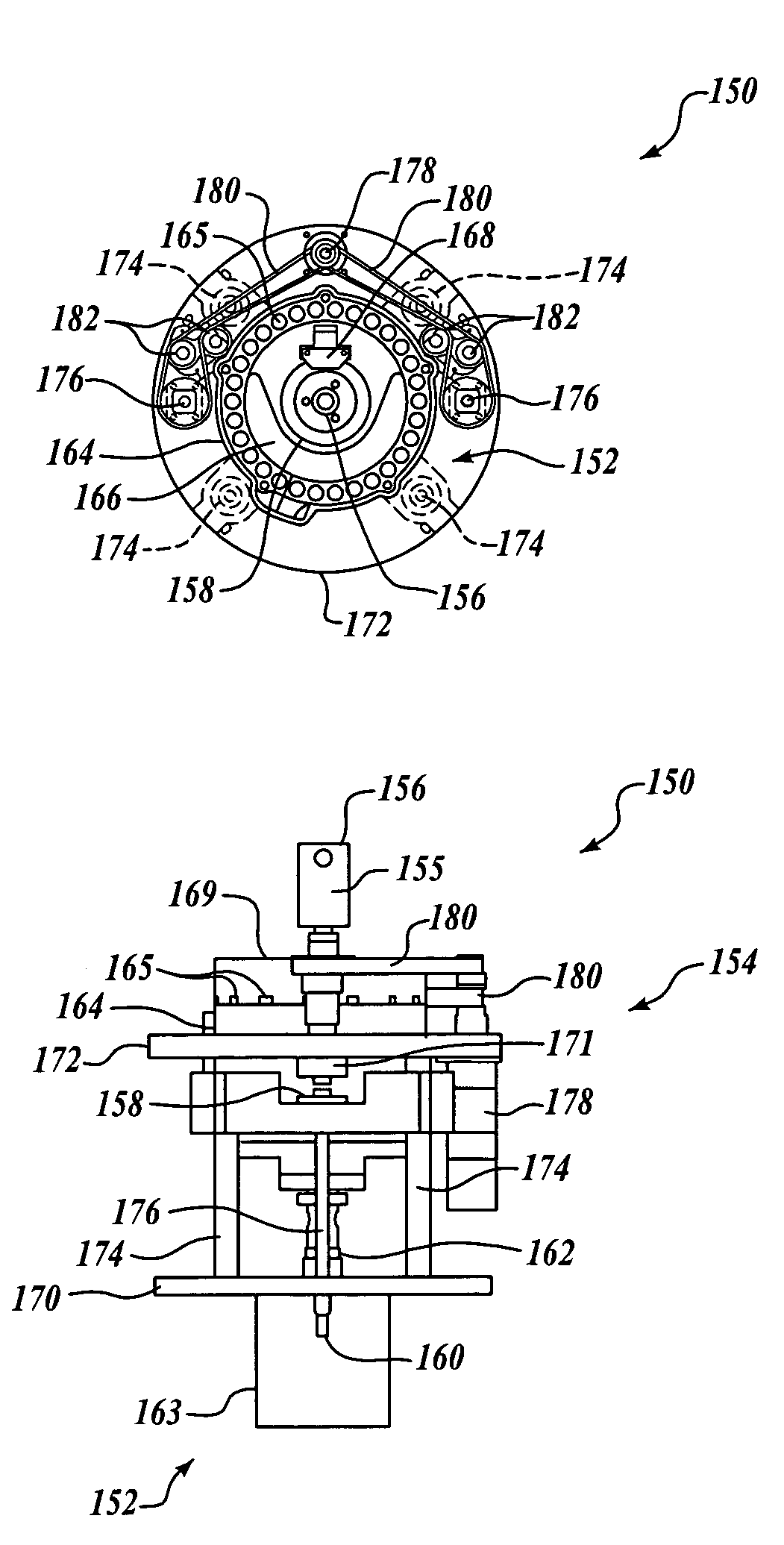
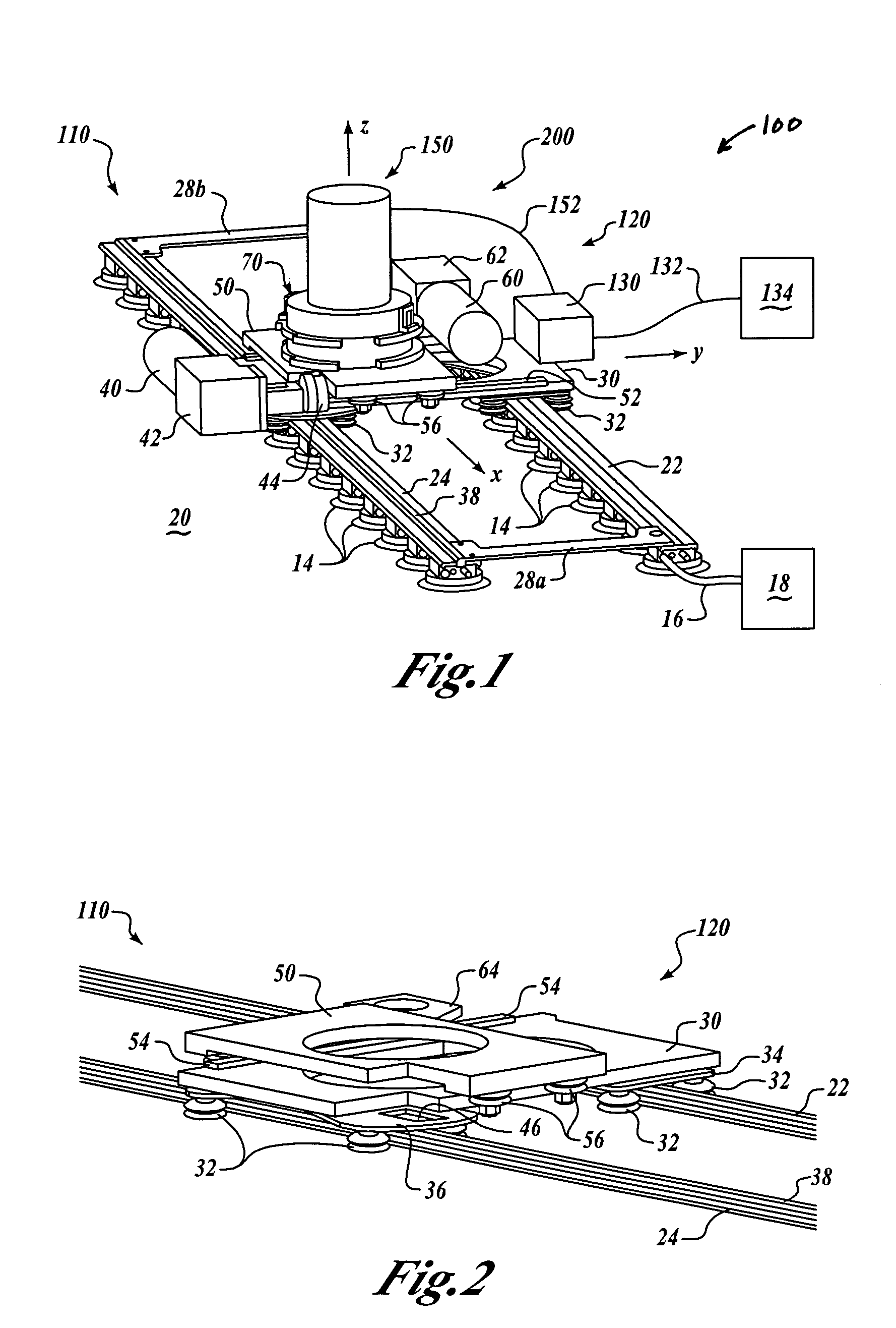
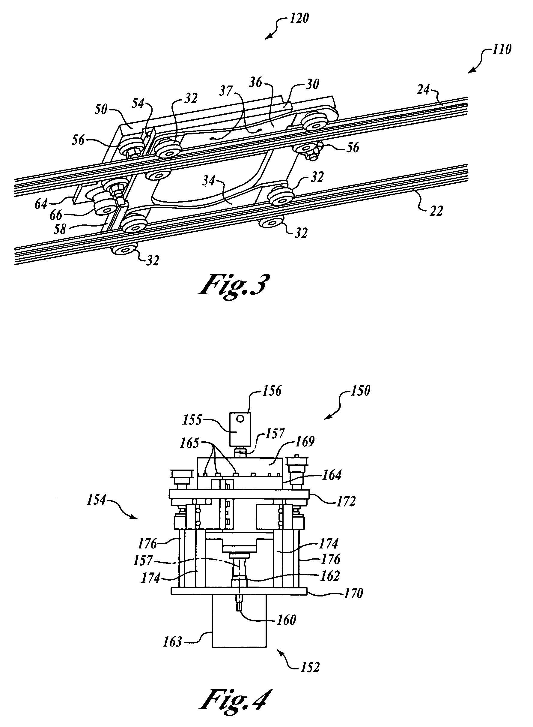
[0014]FIG. 1 is an upper isometric view of a manufacturing assembly 100 having a servo-controlled tool assembly 150 in accordance with an embodiment of the invention. In this embodiment, the manufacturing assembly 100 includes a track assembly 110 controllably attachable to a workpiece 20, and a carriage assembly 120 moveably coupled to the track assembly 110. A controller 130 is mounted on the carriage assembl...


PUM

PropertyMeasurementUnit
Flexibilityaaaaaaaaaa
Distanceaaaaaaaaaa

Abstract

Apparatus and methods for servo-controlled manufacturing operations are disclosed. In one embodiment, an apparatus includes a base member, a drive platform spaced apart from the base member by a separation distance, and a plurality of guide members extending between the drive platform and the base member. At least one of the drive platform and the base member are moveable along the guide members to increase or decrease the separation distance. The apparatus also includes a drive member operatively coupled between the drive platform and the base member, and a servo motor operatively coupled to the drive member. As the servo motor drives the drive member, the separation distance is varied. In an alternate embodiment, a manufacturing tool may be coupled to at least one of the drive platform and the base member.

Description

BACKGROUND OF THE INVENTION[0001]The fabrication of large structures may involve the performance of a large number of manufacturing operations on the structure, such as the drilling of a large number of holes. Conventional structures that require a large number of manufacturing operations include, for example, aircraft, missiles, ships, railcars, sheet metal buildings, and other similar structures. In particular, conventional aircraft fabrication processes typically involve the drilling of a large number of holes in wing sections of the aircraft to allow these sections to be attached to each other and to the airframe.[0002]A variety of devices have been developed to facilitate drilling operations involving the drilling of a large number of holes. For example, U.S. Pat. No. 4,850,763 issued to Jack et al. discloses a drilling system that includes a pair of rails temporarily attached to an aircraft fuselage. A support carriage is slideably coupled to the rails and supports a drill ass...

Claims


Application Information

Patent Timeline
IPC IPC(8): B23B47/00B23B35/00B23Q5/38
CPCB23B35/00B23Q5/385B23B2215/04B23Q2210/008Y10T408/03Y10T408/5612Y10T408/5628Y10T408/554Y10T409/306384Y10T408/165Y10T409/303808
Inventor BUTTRICK, JR., JAMES N.
Owner THE BOEING CO
Why Eureka
Try Eureka