
Percolation testing apparatus and method

a testing apparatus and percolation technology, applied in the direction of instruments, porous material analysis, weighing by absorbing components, etc., can solve the problem of inaccurate testing method implementation

Active Publication Date: 2007-09-11
KRISTIANSEN ROBERT
View PDF13 Cites 6 Cited by
  • Summary
  • Abstract
  • Description
  • Claims
  • Application Information

AI Technical Summary

Benefits of technology

"The present invention is a percolation testing apparatus that allows for accurate and consistent testing of soil or other media. The apparatus includes two detectors that are vertically adjustable and a control circuit that provides signaling to the detectors. The detectors are set to specific elevations and the water drops to the lower detector. The apparatus can be used with multiple test holes simultaneously and can be refilled with water for multiple test runs. The apparatus simplifies the testing process and reduces the time and effort required for soil testing."

Problems solved by technology

This testing method implemented is inaccurate since the art records distance by marking a medium at fixed time intervals.

Method used


Image

  • Percolation testing apparatus and method
  • Percolation testing apparatus and method

Examples


Embodiment Construction

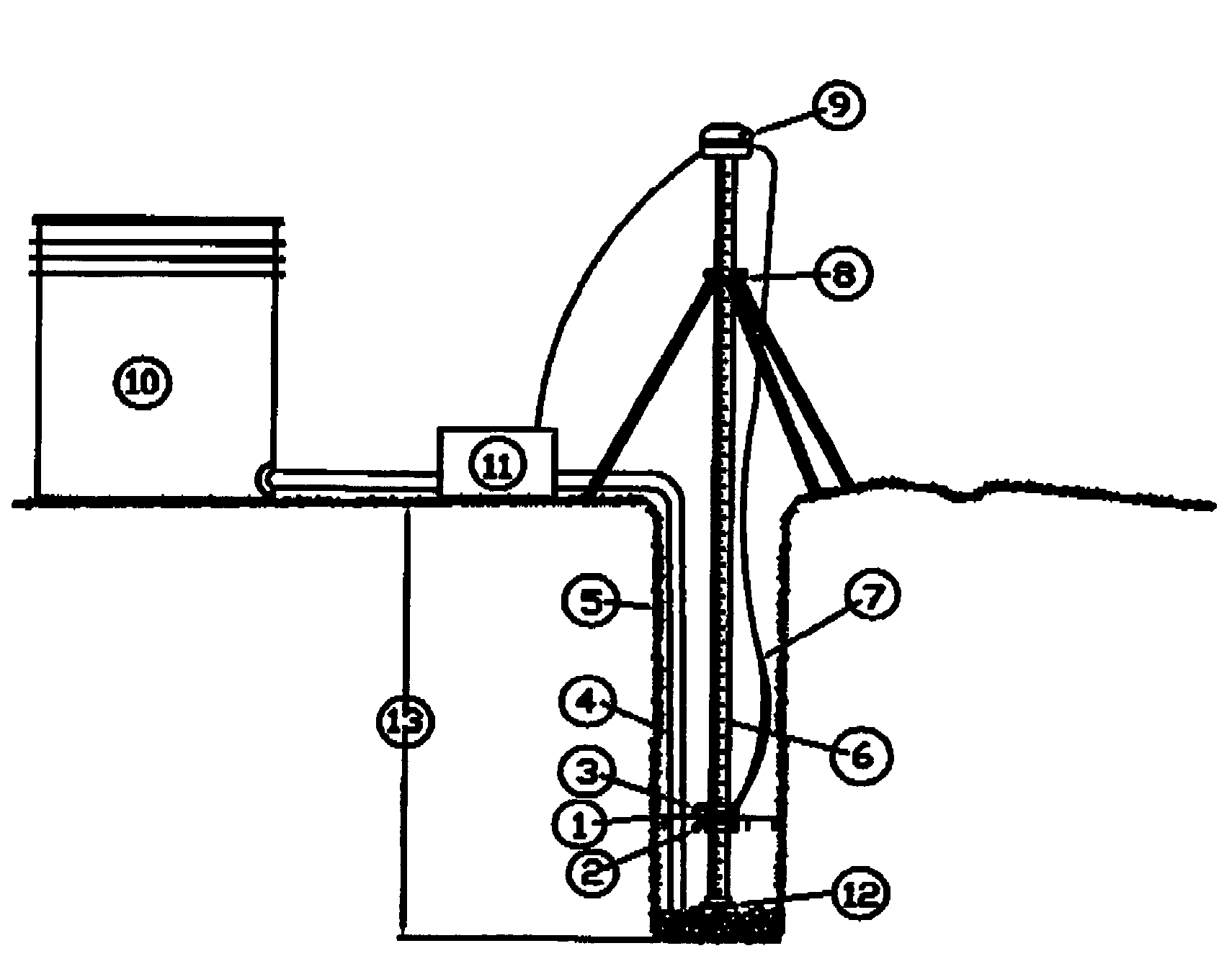
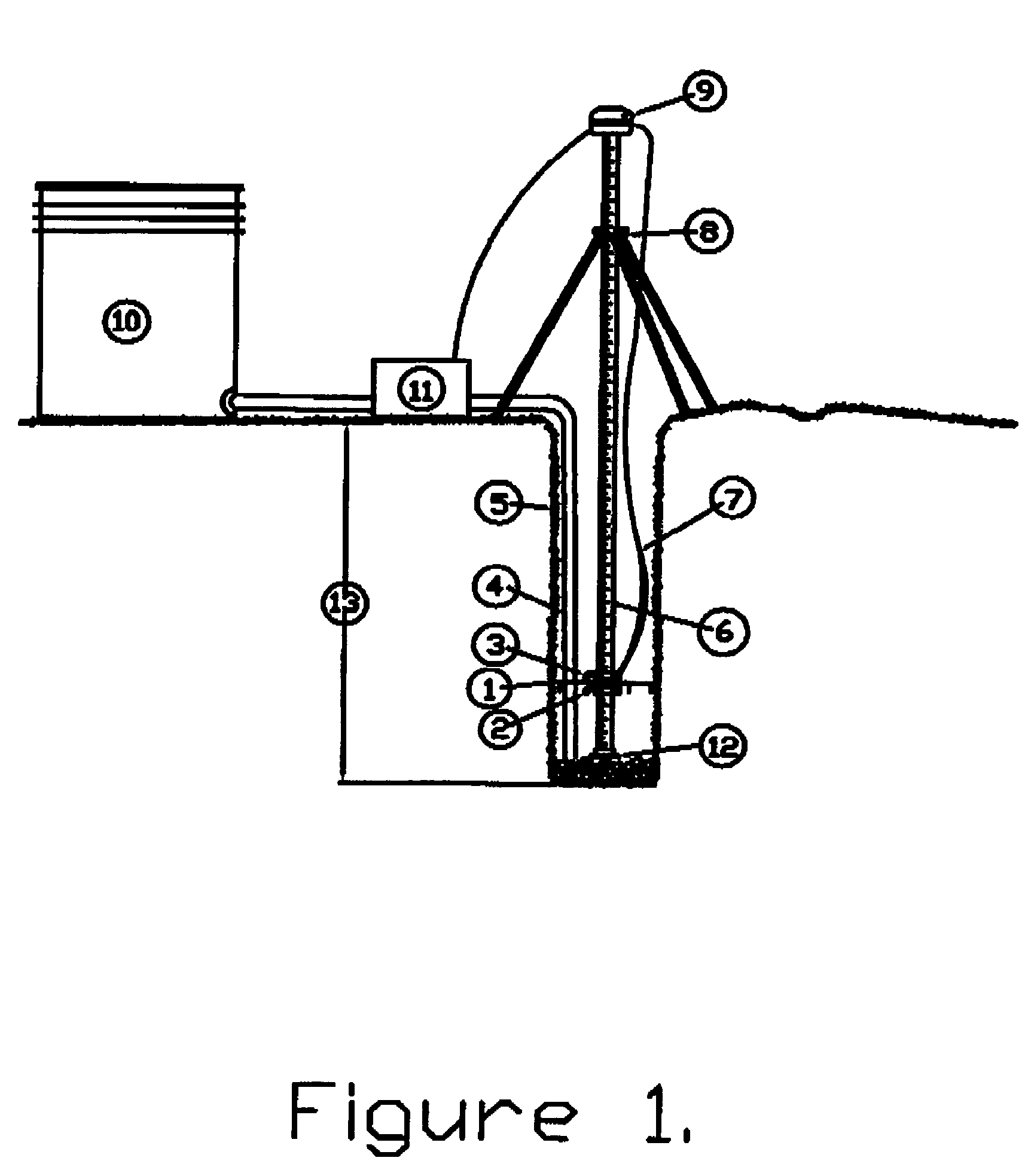
[0004]The present invention enables anyone with minimal skill to conduct accurate soils testing consistent with locally accepted methods. This testing apparatus has two detectors which are vertically adjustable on a scaled vertical member. The said vertical member rests on top of the gravel placed at the bottom of the test hole. Above the test hole, the main vertical member is horizontally supported by a vertically adjustable tripod assembly. Each detector is connected to the control circuit which as shown in the drawing may be mounted on the main vertical support or set near the test hole. The control circuit provides signaling to the timer to start, stop and store times. Additionally, the control circuit drives the control valve which provides source water as needed during repetitive test runs. Finally, the control circuit provides hole filled notification and test complete alarms (audible and visual). The timer circuit can be integrated with the control circuit or a stand-alone t...


PUM

PropertyMeasurementUnit
elevationaaaaaaaaaa
water absorptionaaaaaaaaaa
elapsed timeaaaaaaaaaa

Abstract

An apparatus and method which accurately quantifies the percolation rate of soils, or other materials. This invention unlike prior arts measures the time elapsed for water to drop in a percolation test hole between two fixed points. The elevation of the water is electronically detected which provides signaling to control circuitry that starts and stops an electronic timer and other peripheral circuitry to automate testing. The information gathered is typically used for the design of wastewater and storm water disposal systems.

Description

BACKGROUND OF THE INVENTION[0001]Percolation testing has long been a method to identify the absorption and treatment properties of soil or other media. In the conventional or current method a test hole is dug to the depth of the proposed disposal field system and a couple inches of gravel is placed in the bottom. The hole is then filled with water to presoak the soils. After the hole is empty, water is poured into the test hole to a specified elevation typically marked on a stick with a nail or a line. A second mark is placed on the same stick a measured distance below the first. As the water passes the first mark a start time is recorded and the waters decent is constantly monitored until the second line is reached by the top of the water. The ending time is recorded when the water level reaches the second (or lower) mark. This timing of the water dropping between the upper and lower mark is repeated until two recorded runs are the same showing a “stabilized” percolation rate. This...

Claims


Application Information

Patent Timeline
Patent Type & Authority Patents(United States)
IPC IPC(8): G01N15/08
CPCG01N15/0893G01N2015/0873
Inventor KRISTIANSEN, ROBERT
Owner KRISTIANSEN ROBERT
Learn More