High efficiency bowl mill

a bowl mill and high-efficiency technology, applied in the field of bowl mill pulverizers, can solve the problems of increased throughput, uneven material on the grinding table to be provided to each grinding roller, and ineffective control of the material bed, etc., and achieve the effect of high-efficiency pulverizer and high-efficiency pulverizer

Active Publication Date: 2007-09-11
SCHENCK PROCESS LLC
View PDF9 Cites 20 Cited by
  • Summary
  • Abstract
  • Description
  • Claims
  • Application Information

AI Technical Summary

Benefits of technology

[0016]Still another object of the present invention is to provide a high efficiency pulverizer in which the material bed is conditioned and in which air flow is re-directed.
[0019]The high efficiency bowl mill includes at least a plow and a deflector. The plow is positioned behind a grinding roll. As the grinding table rotates, the grinding rolls pulverize material on the grinding surface, and that pulverized material interacts with the plow. The plow loosens any material that becomes compacted on the grinding surface by the grinding rolls.
[0021]In one aspect of the present invention, the high efficiency bowl mill also includes an inverted cone mounted in the separator body. The inverted cone has an outlet at the bottom thereof that is positioned over the center of the grinding table. Coarse material for pulverization is ejected from this outlet. The ejected material could be material previously pulverized by the high efficiency bowl mill and rejected by a classifier, or could be material never before introduced to the high efficiency bowl mill. The outlet is positioned just over the grinding rolls. In other words, the outlet is positioned as far down in the separator body as possible without contacting the grinding rolls. This positioning restricts redirected air from entering the inverted cone. Alternatively, without departing from the essence of the present invention the cone outlet could be made smaller and possibly even extend below the grinding rolls a certain distance from the grinding table so as to thereby provide a clear passage for particle flow.

Problems solved by technology

However, too great an increase in rotational speed results in unstable operation, known as a rumble mill condition, that does not result in an increase in throughput.
Other problems with known bowl mills relate to the condition of the material on the grinding table, often referred to as the material bed.
In many bowl mills the material bed is not controlled for effective grinding.
That is, the material on the grinding table to be provided to each grinding roller is not uniform across the surface of the grinding table, with some surface areas of the grinding table perhaps not having any material thereon, and with other surface areas of the grinding table having differing depths of material thereon.
The retaining of the material on the grinding table surface gives rise to at least one problem.
In addition to coarse particles, the damming rolls also keep fine particles of materials on the grinding table surface, resulting in an over pulverization of the material.
No existing techniques are known which both address the problems associated with increased centrifugal force and the problems associated with the condition of the material bed discussed above.

Method used


Image

  • High efficiency bowl mill
  • High efficiency bowl mill
  • High efficiency bowl mill

Examples


Embodiment Construction

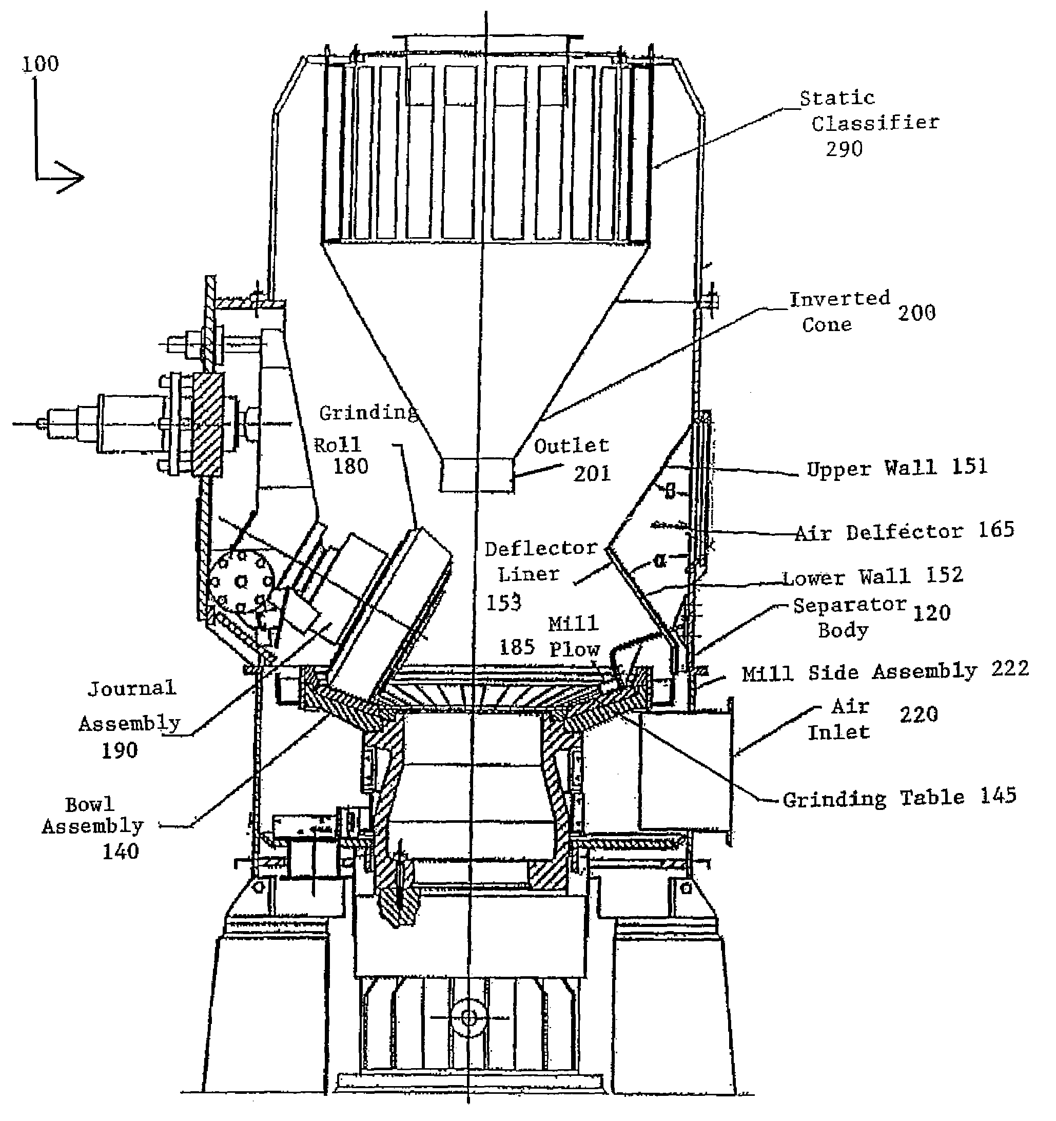
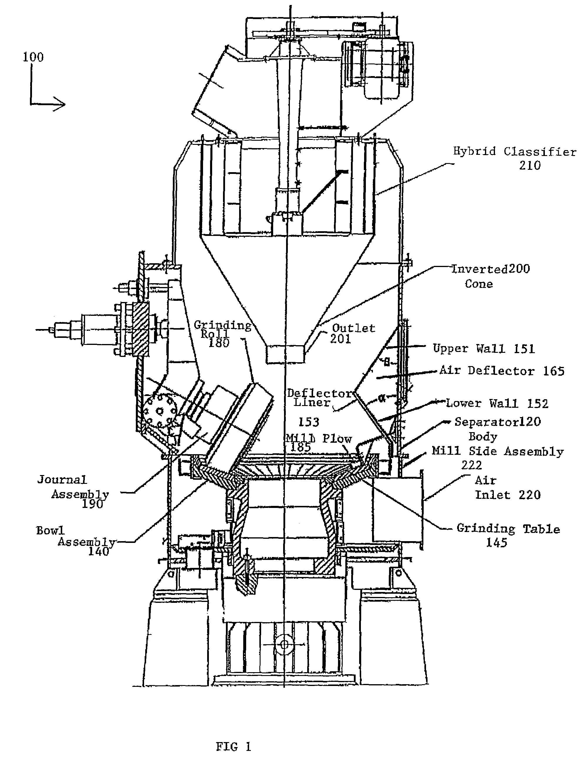
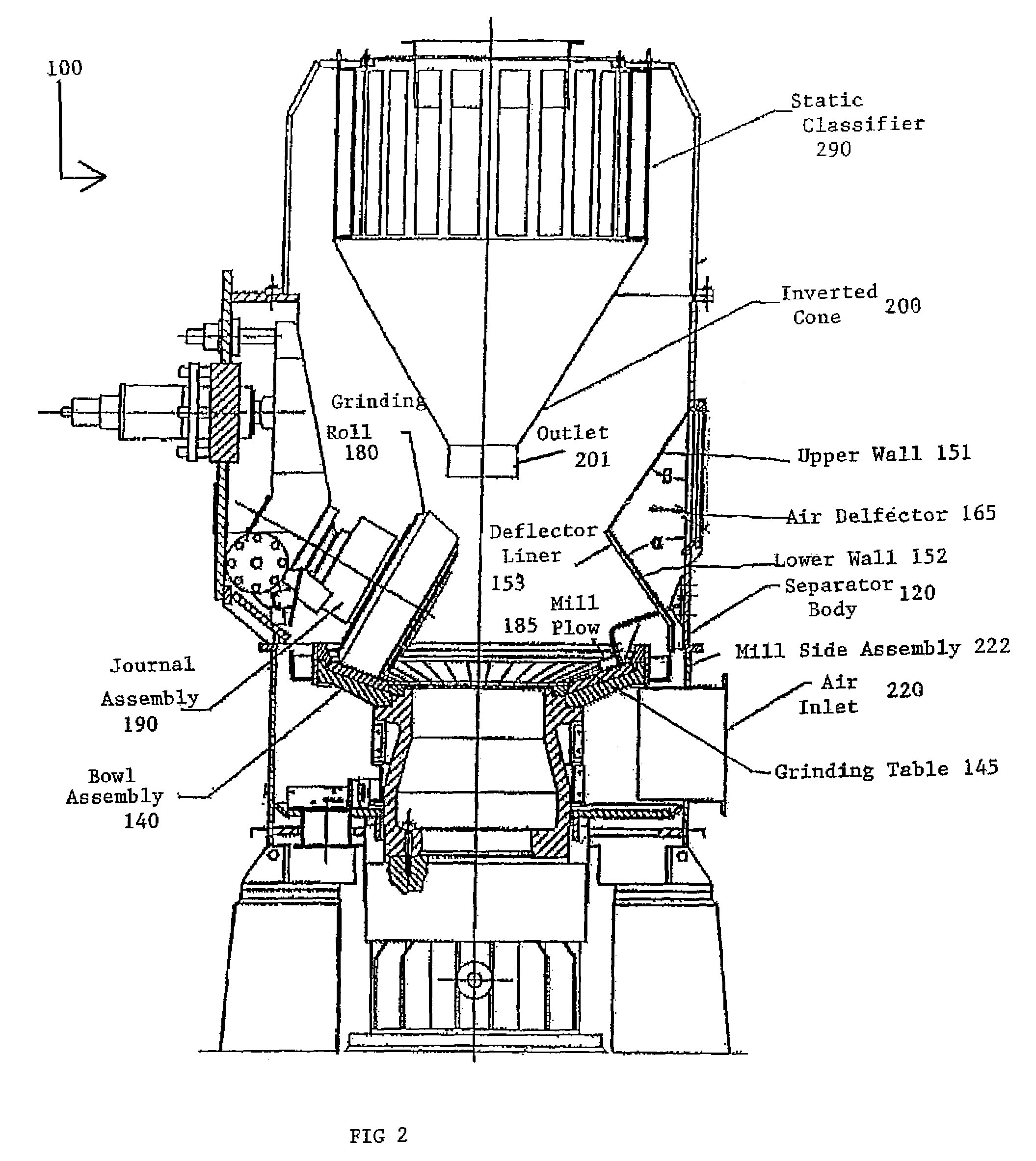
[0030]FIGS. 1 and 2 depict a high efficiency pulverizing bowl mill, generally designated by reference numeral 100, constructed in accordance with the present invention. The high efficiency pulverizing bowl mill 100 as illustrated in FIG. 1 and FIG. 2 includes a substantially closed separator body 120. A bowl assembly 140 is mounted on a shaft (not shown), which in turn is operatively connected to a suitable drive mechanism (not shown) so as to be capable of being rotatably driven thereby. A plurality of grinding rolls 180, preferably three in number in accord with conventional practice, are each suitably supported within the interior of the separator body 120 by an associated journal assembly 190 so as to be equidistantly spaced one from another around the circumference of the separator body 120. In the interest of maintaining clarity of illustration in the drawing, only one such grinding roll 180 and journal assembly 190 have been shown in FIG. 1 and in FIG. 2.

[0031]The material, e...


PUM


Abstract

A high efficiency bowl mill (100) is provided by the present invention. Included in the high efficiency bowl mill (100) is a plow (185) that is downstream of a grinding roll (180) on a grinding surface (145). The plow (185) loosens material that has been compacted by the grinding roll (180). Also included is a deflector (165) that redirects an air stream so as to pick up material loosened by the plow (185) and deposit material requiring further grinding. An outlet (201) of an inverted cone (200) is positioned so as to deposit material for pulverization on the grinding surface (145) and to restrict the air stream from entering the inverted cone (200).

Description

FIELD OF THE INVENTION[0001]The present invention is related to bowl mill pulverizers of the type that are used to effect therewith the pulverization of solid fossil fuels in particular, but it is to be understood are also capable of being used to effect therewith the pulverization of other materials such as gypsum, cement, minerals, etc., and more particularly to a high efficiency bowl mill pulverizer.BACKGROUND OF THE INVENTION[0002]Pulverizers for grinding different type materials are well known in the prior art. Pulverizers are also known as mills. Solid fossil fuels such as coal are one such material wherein there exists a need to grind the material in order to render the solid fossil fuel suitable for use in certain applications, although there are other materials such as gypsum, cement, minerals, etc. that need to be subjected to pulverization as well in order to permit their use in various applications. Fossil fuel fired power generation systems represent one such applicatio...

Claims


Application Information

Patent Timeline
Patent Type & Authority Patents(United States)
IPC IPC(8): B02C15/04B02C15/00
CPCB02C15/001B02C15/04B02C2015/002
Inventor CHEN, MICHAEL MCHEN, JIANRONGPODMOKLY, DAVID M.
Owner SCHENCK PROCESS LLC
Why Eureka
Try Eureka