Vibration control device

a technology of vibration control and control device, which is applied in the field of vibration isolation mechanisms, can solve the problems of affecting the quality of affecting the quality of the listening or viewing experience of individuals, etc., and achieves the effects of reducing excess noise, wide weight range, and being easy to manufactur

Active Publication Date: 2007-09-11
KENNARD INDS
View PDF10 Cites 7 Cited by
  • Summary
  • Abstract
  • Description
  • Claims
  • Application Information

AI Technical Summary

Benefits of technology

[0013]With the above problems and limitations of the known art in mind, the present invention was developed with the goals of providing a vibration isolating device which is inexpensive to produce, durable, and facile to use with little or no instruction, so as to be readily accessible and usable by the anyone, including the most ardent audiophile as well as the less sophisticated user, including those with modest financial means. It is further among the advantages of the present invention that the new vibration reduction device is suitable for manufacture in a variety of sizes or models so as to be capable of handling various sizes of loads and a variety of applications, such as excess noise reduction and vibrations which can affect readings of scientific instruments. It is further the objective that the present invention be less sensitive to various weight differences in the equipment to be supported such that a given device can be used to support a wide weight range. It is further intended that the new vibration control device be used as a plurality of same and the number and relative positions of such device in relation to the object being supported thereon be readily selectively variable, to suit the user's needs or particular preferences.
[0014]It is further among the objects of the invention, having the features indicated, the new vibration control device not require a source of pressurized air to function, or any extraneous equipment, whether powered, or otherwise, and that it be light-weight and small, for facile placement where needed, that it isolate the unwanted vibration and disperse the energy throughout the device and thus isolate the equipment with which it is used from vibration, rather than simply draining the vibration to the ground.
[0015]When the new vibration control devices are used as described hereafter with audio equipment for vibration isolation, the resultant reduction of unwanted sounds (“noise”); i.e., lowering of the “noise floor” allows for greater dynamics and a perception of increased volume levels. Some users will note that the volume can actually be turned down, relative to their usual listening levels, and good enjoyment of the music still obtained.

Problems solved by technology

One of the main causes of such performance variations in such equipment is vibration, particularly that which is referred to as “micro” vibration within the audio equipment, such as compact disk (“CD”) players, preamplifiers, amplifiers, phonograph stages, and turntables.
Other, “macro” vibrations may also happen when a door is slammed, the equipment is bumped, or even from floor movement caused by a person walking in the room.
The irregularities in sound or visual quality of the product caused by the vibration are very distracting to the experienced observer and significantly decreases the quality of the listening or viewing experience for these individuals.
Similarly high technology and laboratory equipment such as microscopes, scales, etc. may likewise be negatively affected by vibrations, even to the extent of causing data produced or collected thereon to be unreliable.
However, each of these different methods has certain limitations or disadvantages.
Some of the known methods, such as air isolation devices and some seismic sinks are quite expensive and also require a source of pressurized air.
Products made of SORBOTHANE material are limited in the capability to attenuate vibration.
Spikes and cones “drain” vibration to the ground or other support surface, rather than actually isolating the performance device from the vibration; and sand boxes, by definition, include the use of sand, which can be very messy and necessarily creates the risk of inadvertent introduction of sand particles and dust into expensive performance equipment, accessories, tapes, compact disks, and anything else in the vicinity of use of the sand.
However, the device described in these applications are very weight sensitive, thus requiring varying classes of the device to accommodate the varying weights of the equipment.
However, the energy absorption and dispersion characteristics are not ideal due to the interaction between the hard bearings and the resilient retainer design.

Method used


Image

  • Vibration control device
  • Vibration control device
  • Vibration control device

Examples


Embodiment Construction

[0025]According to the embodiment(s) of the present invention, various views are illustrated in FIG. 1-6 and like reference numerals are being used consistently throughout to refer to like and corresponding parts of the invention for all of the various views and figures of the drawing. Also, please note that the first digit(s) of the reference number for a given item or part of the invention should correspond to the Figure number in which the item or part is first identified.

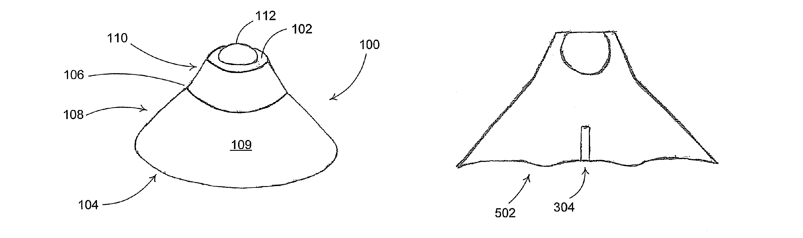
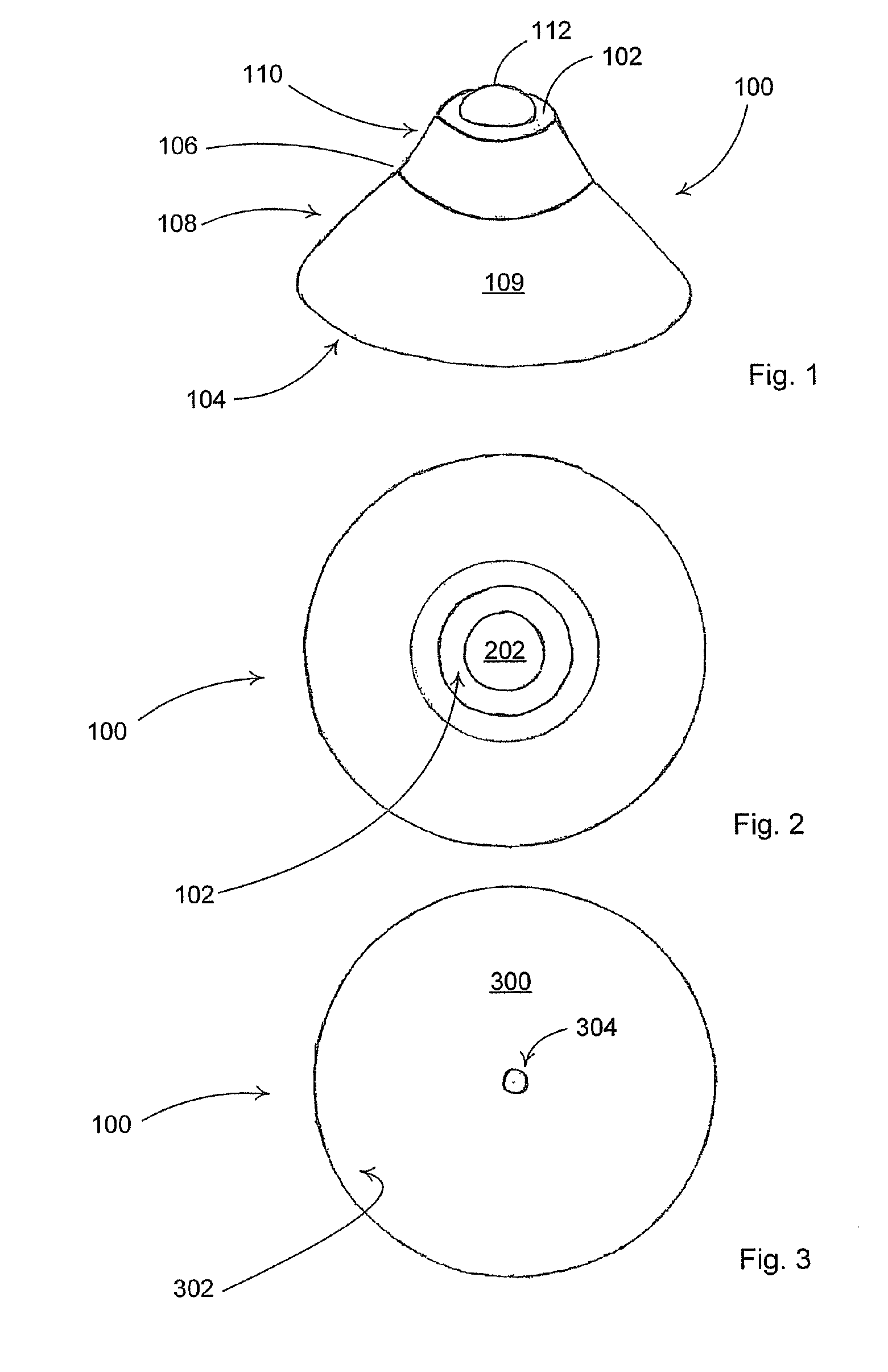
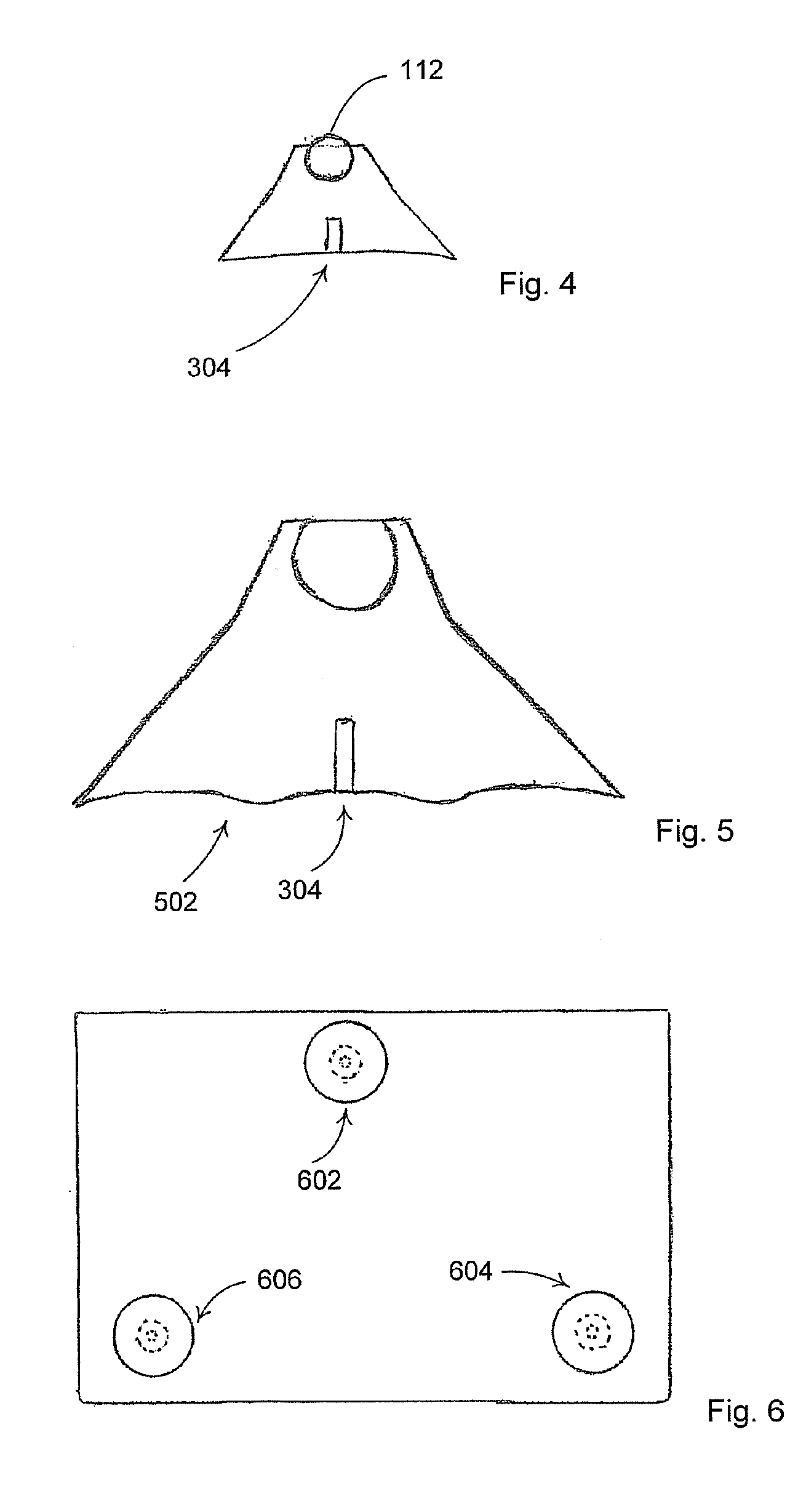
[0026]One embodiment of the present invention comprising a frustum-conical shaped unitary main body made of a pliable material having a top surface and a bottom surface and conical side walls extending from the top surface to the bottom surface and where the conical side walls are formed with a angular variation in the downward and outward slope and further where the bottom surface is formed with a slight concavity and comprising a non-pliable spherical protrusion integral with the main body and extending from t...


PUM


Abstract

A device for control of the effects of vibrations on vibration sensitive equipment when a plurality of the devices are placed on a support surface and in operative contact with the vibration sensitive equipment where said device is a unitary piece of a soft, pliable substance having a hardened round crown portion.

Description

CROSS REFERENCES TO RELATED APPLICATIONS[0001]This patent application claims priority to U.S. Provisional Patent Application Ser. No. 60 / 521,360 filed Apr. 8, 2004.BACKGROUND OF INVENTION[0002]1. Field of Invention[0003]This invention relates generally to the field of vibration isolation mechanisms, more particularly, to a vibration control device which provides improved vibration control noise reduction in an economical, easy to use device which is perfectly suited, for example, for improving noise reduction, when used with audio equipment.[0004]2. Background Art[0005]People who spend a significant amount of time listening to music often become particularly astute to hearing extraneous variations, which can be caused by a number of factors. One of the main causes of such performance variations in such equipment is vibration, particularly that which is referred to as “micro” vibration within the audio equipment, such as compact disk (“CD”) players, preamplifiers, amplifiers, phonogr...

Claims


Application Information

Patent Timeline
Patent Type & Authority Patents(United States)
IPC IPC(8): F16M13/00F16F1/373
CPCF16F1/373F16F2230/14Y10S248/917
Inventor KENNARD, IV, SAMUEL M.
Owner KENNARD INDS
Why Eureka
Try Eureka