Structure of signal cable connector

a signal cable and connector technology, applied in the direction of coupling device connection, electrical apparatus, coupling protection earth/shielding arrangement, etc., can solve the problems of stiff challenge in wire stripping, soldering and wire connection, and the excess of ribbon cable requires more space, so as to minimize the operation time and facilitate assembly. , the effect of optimizing the yield

Inactive Publication Date: 2007-09-11
UNICONN CORP
View PDF4 Cites 122 Cited by
  • Summary
  • Abstract
  • Description
  • Claims
  • Application Information

AI Technical Summary

Benefits of technology

[0010]According to the foregoing assembly, fitting conducting wires of the wire strand into furrows of the plastic blocks, and then concealing said plastic blocks under the metal blocks so as to form into one block unit; further, stripping said conducting wires of the wire strand, which are well aligned and affixed on wire block, by laser cutting so as to optimize the yield while minimizing the operation time. After wire stripping, soldering the ground wires on ground circuits on two sides of the circuit board. The plastic blocks are well concealed under the metal blocks by forks on flanks of said metal blocks. And, the circuit board is thus well fitted in the plastic blocks that are concealed under the metal blocks. In another word, a sub-assembly unit is formed after fitting the circuit board comprising ground circuits into plastic blocks, and concealing said plastic blocks under metal blocks. Later on, soldering the signal wires on signal circuits of the circuit board, and folding

Problems solved by technology

Also, more space is required to accommodate the excess of ribbon cable.
No doubt, solder of many tiny pins on a compact surface that easily causes short circuit is quite a challenge.
In addition, while the wire strand 53 is connected to the circuit board52, the conducting wires cannot be well affixed that would cause stiff challenge in wire stripping, soldering and wire connection.
Consequently,

Method used


Image

  • Structure of signal cable connector
  • Structure of signal cable connector
  • Structure of signal cable connector

Examples


Embodiment Construction

[0017]Desirable structure, assembly and features of the present invention will be better understood from the detailed description and drawings that follow, in which various embodiments of the disclosed invention are illustrated by way of example.

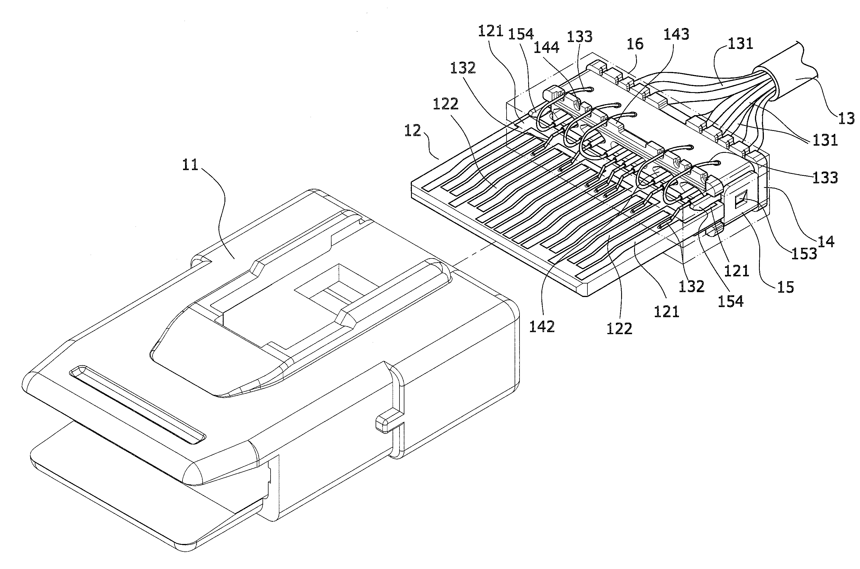
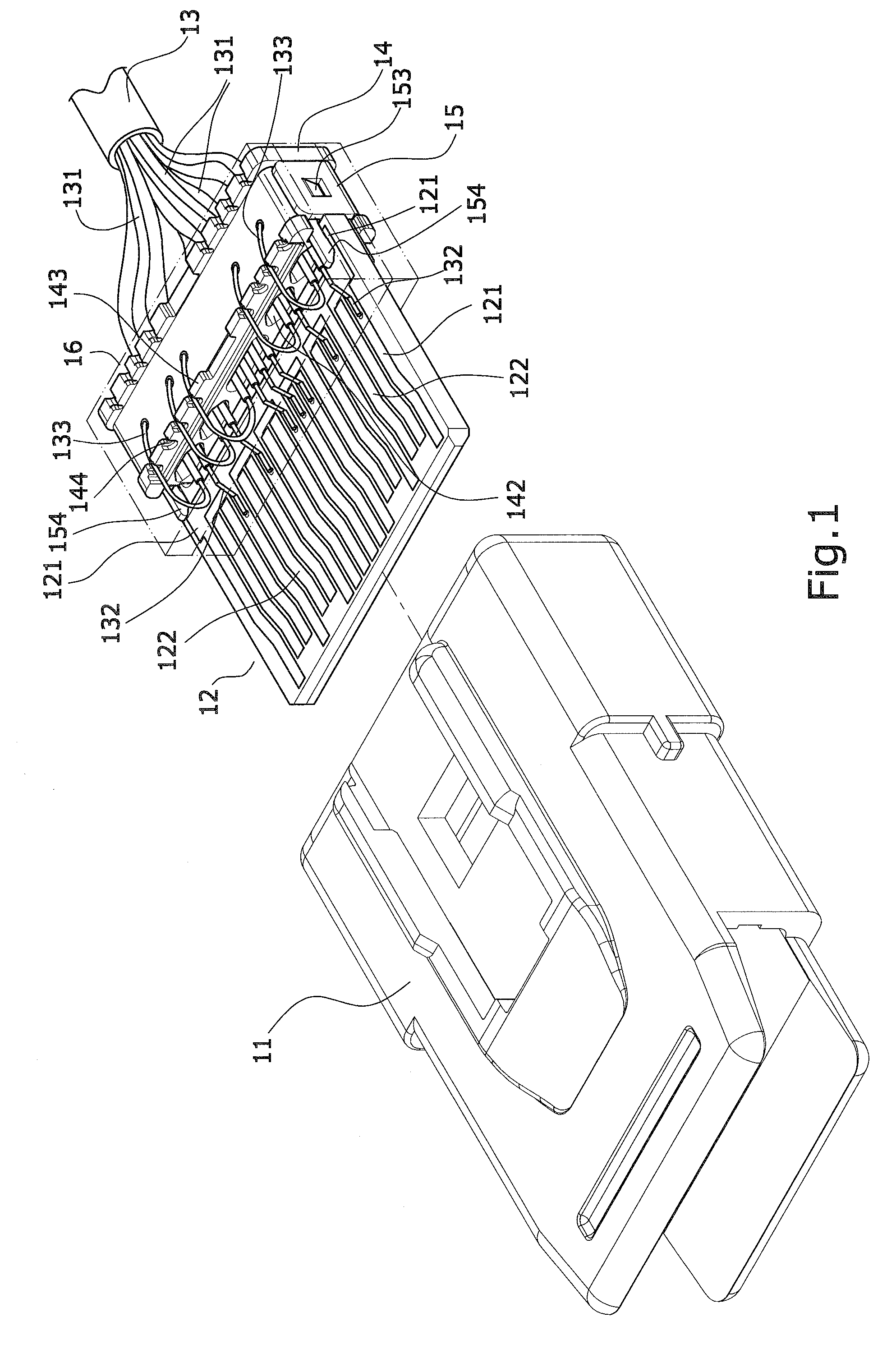
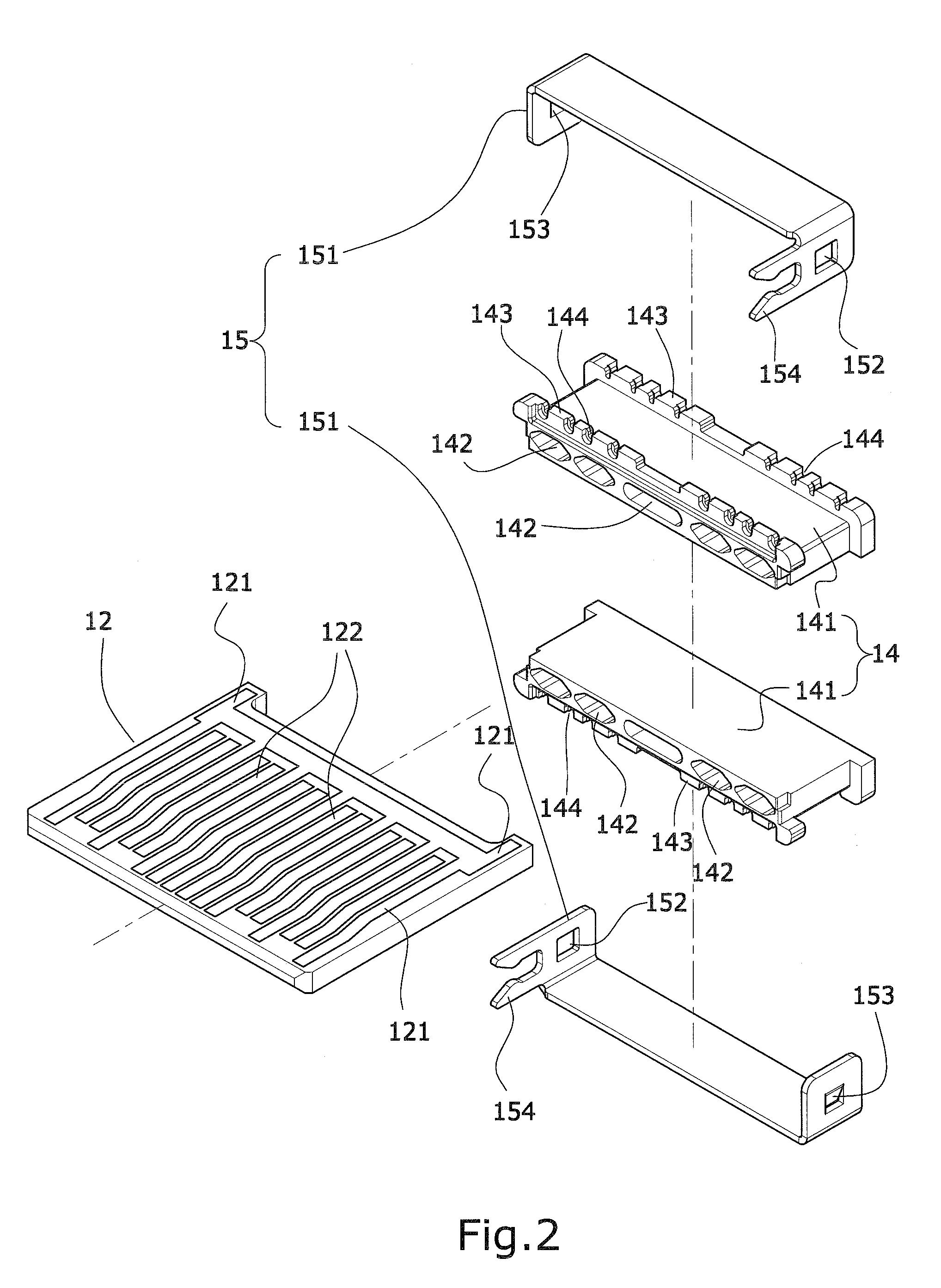
[0018]As shown in FIGS. 1 and 2, the “structure of signal cable connector” mainly comprises an enclosure11, a circuit board12 and a wire strand13 so as to be connected to the signal cable between the hard disk and the computer's main board. The characteristic lies in: there are a wire block14 and a ground block15 at solder end of the wire strand13; the wire block14 is composed by a pair of conjugate plastic blocks141 where a plurality of furrows142 running lengthwise are formed on the surface, a plurality of ridges143 are formed around front and rear openings, and a plurality of grooves incised from said ridges; the ground block15 is composed by a pair of conjugate metal blocks151 comprising a pair of mortise152 and tenon153 and a fork154 pr...


PUM


Abstract

A structure of signal cable connector, which is connected to the signal cable between the hard disk and the computer's main board, comprises at least an enclosure, a circuit board and a wire strand. Wherein a wire block is utilized to affix the signal wires and a ground block to conduct the soldered ground wires so as to minimize the solder points incurred by direct solder of conducting wires on circuit board, resulting in easier assembly and optimized yield.

Description

BACKGROUND OF THE INVENTION[0001]I. Field of the Invention[0002]The present invention relates to a structure of signal cable connector, particularly to a structure of round ribbon cable connector that is connected to the round ribbon cable connecting the hard disk and the computer's main board. The present invention provides separate structures of wire block and ground block to facilitate the assembly and optimize the yield.[0003]II. Description of the Prior Art[0004]The signal cable of the prior art, which is utilized to connect the hard disk and the computer's main board, is a ribbon cable with many conducting wires running parallel to each other on the same flat plane. As a result the ribbon cable is wide, flat and oriented in such a way that can hardly be sharply twisted for connection. Also, more space is required to accommodate the excess of ribbon cable. To have less bulky cable and even greater airflow, the round ribbon cable, which is more manageable and far easier to insta...

Claims


Application Information

Patent Timeline
IPC IPC(8): H01R12/24
CPCH01R9/034H01R13/6658H01R13/6593H01R13/6594H01R13/6585H01R13/65914
Inventor HWANG, MAO-LIN
Owner UNICONN CORP
Why Eureka
Try Eureka