Magnetism detecting device for canceling offset voltage

a technology of offset voltage and magnetic detection device, which is applied in the direction of magnetic measurement, instruments, surveying and navigation, etc., can solve problems such as azimuth errors, and achieve the effect of high precision

Active Publication Date: 2007-09-11
ALPS ALPINE CO LTD
View PDF11 Cites 4 Cited by
  • Summary
  • Abstract
  • Description
  • Claims
  • Application Information

AI Technical Summary

Benefits of technology

[0007]According to a first aspect of the invention, a magnetism detecting device includes a magnetometric sensor that detects magnetism, a bias magnetic field generating unit that applies a bias electric field to the magnetometric sensor while inverting its polarity, a voltage applying unit that applies a first voltage and a second voltage to the magnetometric sensor, the first voltage and the second voltage having the same value and inverted polarities, a detecting unit that detects voltage values obtained for bias magnetic fields of respective polarities, and an operating unit that calculates an azimuth using the voltage values. The detecting unit calculates a first output voltage that is the difference between the first voltage and the voltage value obtained by applying the bias magnetic field of each polarity and a second output voltage that is the difference between the second voltage and the voltage value obtained by applying the bias magnetic field of each polarity, and eliminates an offset voltage included in the first and second output voltages by the difference between the first and second output voltages.
[0008]According to this configuration, by taking the difference between the first and second output voltages calculated by inverting the polarities of the bias magnetic field and the voltage, the offset voltage occurring in a circuit can be eliminated.
[0009]According to a second aspect of the invention, a magnetism detecting device includes a magnetometric sensor that detects magnetism, a bias magnetic field generating unit that applies a bias magnetic field while inverting its polarity, a voltage applying unit that applies a voltage to the magnetometric sensor, a detecting unit that detects voltage values obtained for the bias magnetic fields of respective polarities, and an operating unit that calculates an azimuth using the voltage values. The detecting unit has a switching unit that receives first and second voltage values obtained by applying the bias magnetic fields of the respective polarities and switches between a subtraction of the second voltage value from the first voltage value and a subtraction of the first voltage value from the second voltage value, and eliminates an offset voltage by taking the difference between values before and after switching.
[0010]According to this configuration, by subtracting the first and second voltage values obtained by applying the bias magnetic fields of the respective polarities while switching and by taking the difference of the subtraction result, the offset voltage occurring in the circuit can be eliminated.
[0014]According to this configuration, the azimuth calculation can be performed by use of the difference calculated from the magnetoresistance change. In this case, since the offset voltage occurring in the circuit can be eliminated in the magnetism detecting device according to the first or second aspect of the invention, the azimuth calculation can be performed with higher precision.

Problems solved by technology

However, in the above-described magnetism detecting device, a voltage difference value outputted from an amplifier in a circuit inevitably includes an offset voltage peculiar to the amplifier, which causes an azimuth error.

Method used


Image

  • Magnetism detecting device for canceling offset voltage
  • Magnetism detecting device for canceling offset voltage
  • Magnetism detecting device for canceling offset voltage

Examples


first embodiment

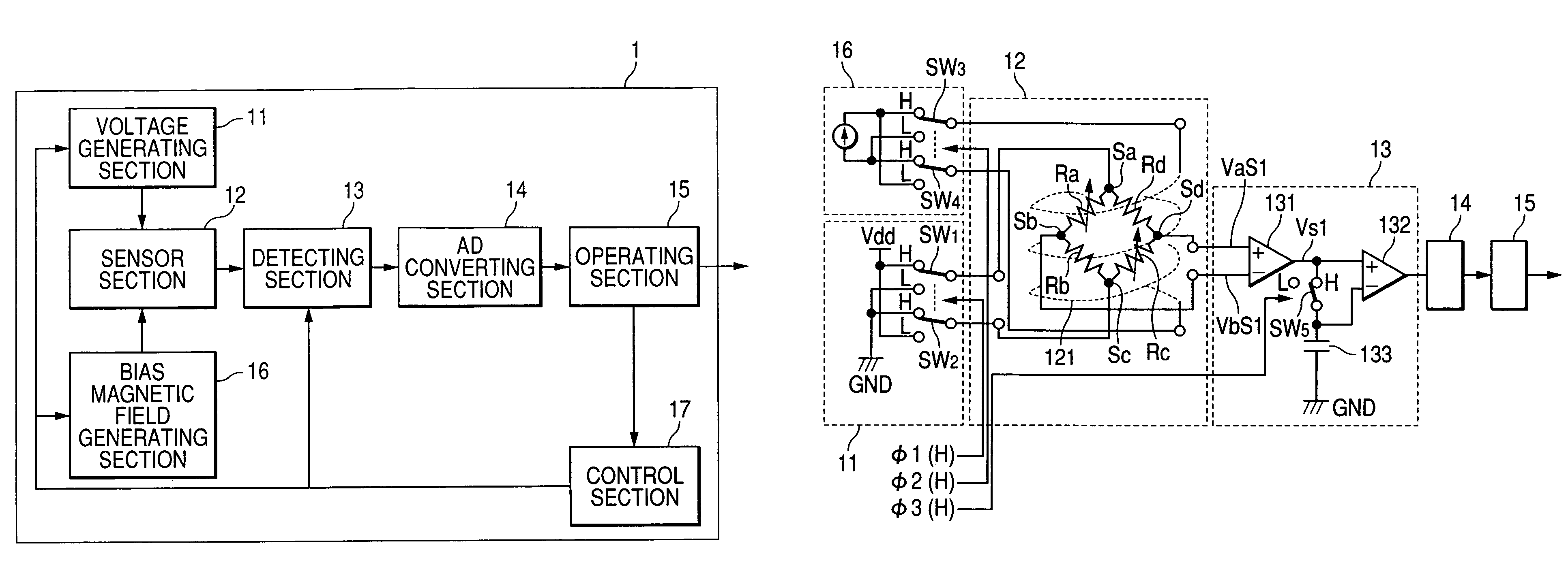
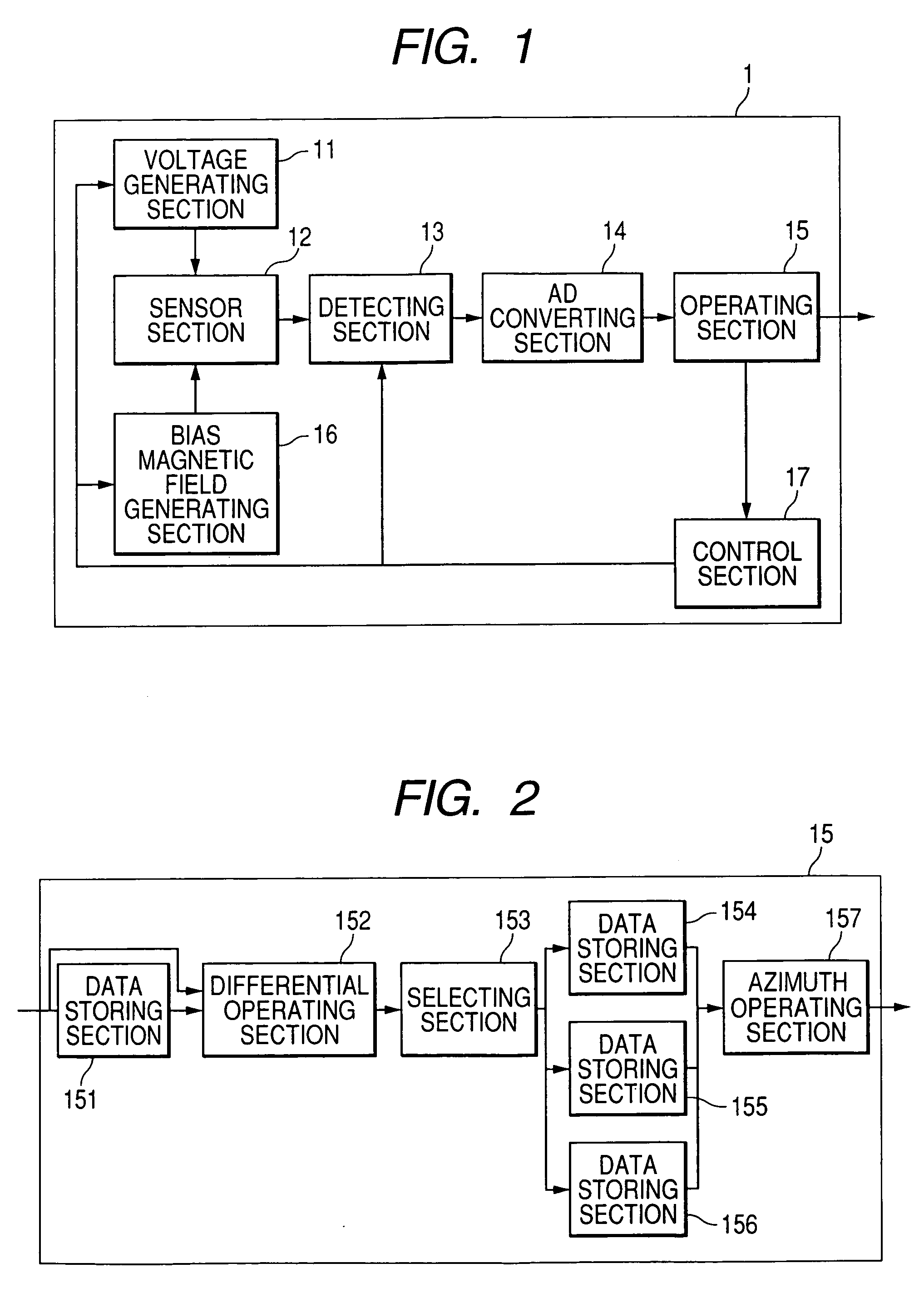
[0033]In the present embodiment, the configuration in which a voltage is applied to a magnetometric sensor while inverting its polarity will be described. That is, in the present embodiment, a voltage of one polarity (for example, positive) is used as a first voltage and a voltage of the other polarity (for example, negative) is used as a second voltage. FIG. 1 is a block diagram showing the schematic configuration of an electronic azimuth meter having a magnetism detecting device according to a first embodiment of the invention.

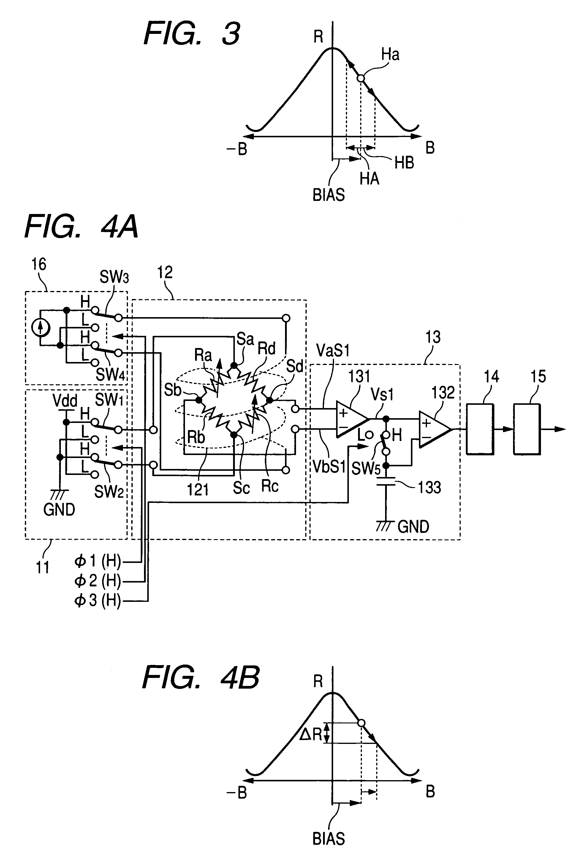
[0034]The magnetism detecting device shown in FIG. 1 primarily has a sensor section 12 that output a voltage value corresponding to a change in geomagnetism, a voltage generating section 11 that alternately applies the first and second voltages (positive and negative voltages) to the sensor section 12 while switching, a bias magnetic field generating section 16 that applies a bias magnetic field to the sensor section 12, a detecting section 13 that detects (...

second embodiment

[0074]In the present embodiment, the configuration of the detecting section in which a subtraction of a second voltage value obtained by use of a bias magnetic field of the other polarity from a first voltage value obtained by use of a bias magnetic field of one polarity, and a subtraction of the first voltage value obtained by use of the bias magnetic field of one polarity from the second voltage value obtained by use of the bias magnetic field of the other polarity are switched. In this configuration, the voltage generating section 11 of the electronic azimuth meter shown in FIG. 1 is omitted so as not to invert the polarity of the voltage.

[0075]Further, according to this configuration, in the detecting section 13, there is provided a switching unit for switching the subtraction of the second voltage value obtained by use of the bias magnetic field of the other polarity from the first voltage value obtained by use of the bias magnetic field of one polarity, and the subtraction of ...


PUM


Abstract

A magnetism detecting device includes a magnetometric sensor, a bias magnetic field generating unit, a voltage applying unit, a detecting unit, and an operating unit. The detecting unit calculates a first output corresponding to a difference between two voltage values each corresponding to the positive and negative bias magnetic fields, and the positive voltage; and a second output corresponding to a difference between two voltage values each corresponding to the positive and negative bias magnetic fields, and the negative voltage. The detecting unit eliminates an offset voltage included in the first output and the second output by taking difference between the first output and the second output.

Description

BACKGROUND OF THE INVENTION[0001]1. Field of the Invention[0002]The present invention relates to a magnetism detecting device and an electronic azimuth meter using the same.[0003]2. Description of the Related Art[0004]When an azimuth is electronically measured, a magnetometric sensor that detects geomagnetism is used. In order to calculate an azimuth by use of a magnetism detecting device having such a magnetometric sensor, a technology has been known in which an alternating current (AC) bias magnetic field is applied to the magnetometric sensor and a voltage outputted from the magnetometric sensor is measured when the bias magnetic field of each polarity is applied thereto. Then, the voltage value is stored in a capacitor, and an azimuth is calculated by use of the difference between the voltage values of the respective polarities. Accordingly, errors due to offset characteristics and hysteresis characteristics peculiar to the magnetometric sensor can be eliminated.[0005]However, i...

Claims


Application Information

Patent Timeline
Patent Type & Authority Patents(United States)
IPC IPC(8): G01R33/02
CPCG01C17/28G01R33/09G01R33/02G01C17/32H10N50/10
Inventor YAMADA, YUKIMITSU
Owner ALPS ALPINE CO LTD
Why Eureka
Try Eureka