Method of broadband constant directivity beamforming for non linear and non axi-symmetric sensor arrays embedded in an obstacle

a constant directivity, beamforming technology, applied in the direction of transducer casings/cabinets/supports, frequency/directions obtaining arrangements, transducer circuits, etc., can solve the problem of only providing redundant information, reducing the spacing between sensors under /2, and posing loss of “look” direction. the effect of preventing the loss of “look direction

Active Publication Date: 2007-09-11
MITEL
View PDF7 Cites 52 Cited by
  • Summary
  • Abstract
  • Description
  • Claims
  • Application Information

AI Technical Summary

Benefits of technology

[0045]According to the present invention, a method is provided for designing a broad band constant directivity beamformer for a non-linear and non-axi-symmetric sensor array embedded in an obstacle having an odd shape (such as a telephone set) where the shape is imposed, for example, by industrial design constraints. In particular, the method of the present invention corrects beam pattern asymmetry and keeps the main lobe reasonably constant o

Problems solved by technology

Although a number of the methods discussed in the above-referenced prior art use specific vectors to shape the beam they, do not deal with the consequences of non-linear or non axi-symmetric arrays on the beampatterns and the resultant possible loss of “look” direction.
Although this method can produce a constant beam pattern or null in given directions at various frequencies it is not designed to produce an identical beam pattern over a continuous frequency band and for various azimuth angle when the array is “asymmetric”.
This procedure is intended to generate a constant beam over a band of frequencies, but is limited to symmetrical free-field arrays.
It should be noted that lowering the inter-sensor spacing under λ/2 only provides redundant information and directly conflicts with the desire to have as muc

Method used


Image

  • Method of broadband constant directivity beamforming for non linear and non axi-symmetric sensor arrays embedded in an obstacle
  • Method of broadband constant directivity beamforming for non linear and non axi-symmetric sensor arrays embedded in an obstacle
  • Method of broadband constant directivity beamforming for non linear and non axi-symmetric sensor arrays embedded in an obstacle

Examples


Embodiment Construction

[0076]The following table contains the different notations used in this specification, from which it will be noted that the frequency dependency for matrices, vectors and scalars, has for the most part been omitted to simplify the notations. Any other specific notations not appearing in Table 1 are defined in the specification.

[0077]

TABLE INotationsNOTATIONSdcomplex vector (column vector)dicomplex vector ith componentdi*complex conjugate of the vector ith componentdHd Hermitian transpose (line vector)dN complex vector (column vector) index Ndθcomplex vector (column vector) index θRComplex MatrixRHComplex Hermitian transpose MatrixIIdentity matrixWHdHermitian productωCircular frequency (=2 πf f: frequency in Hz)

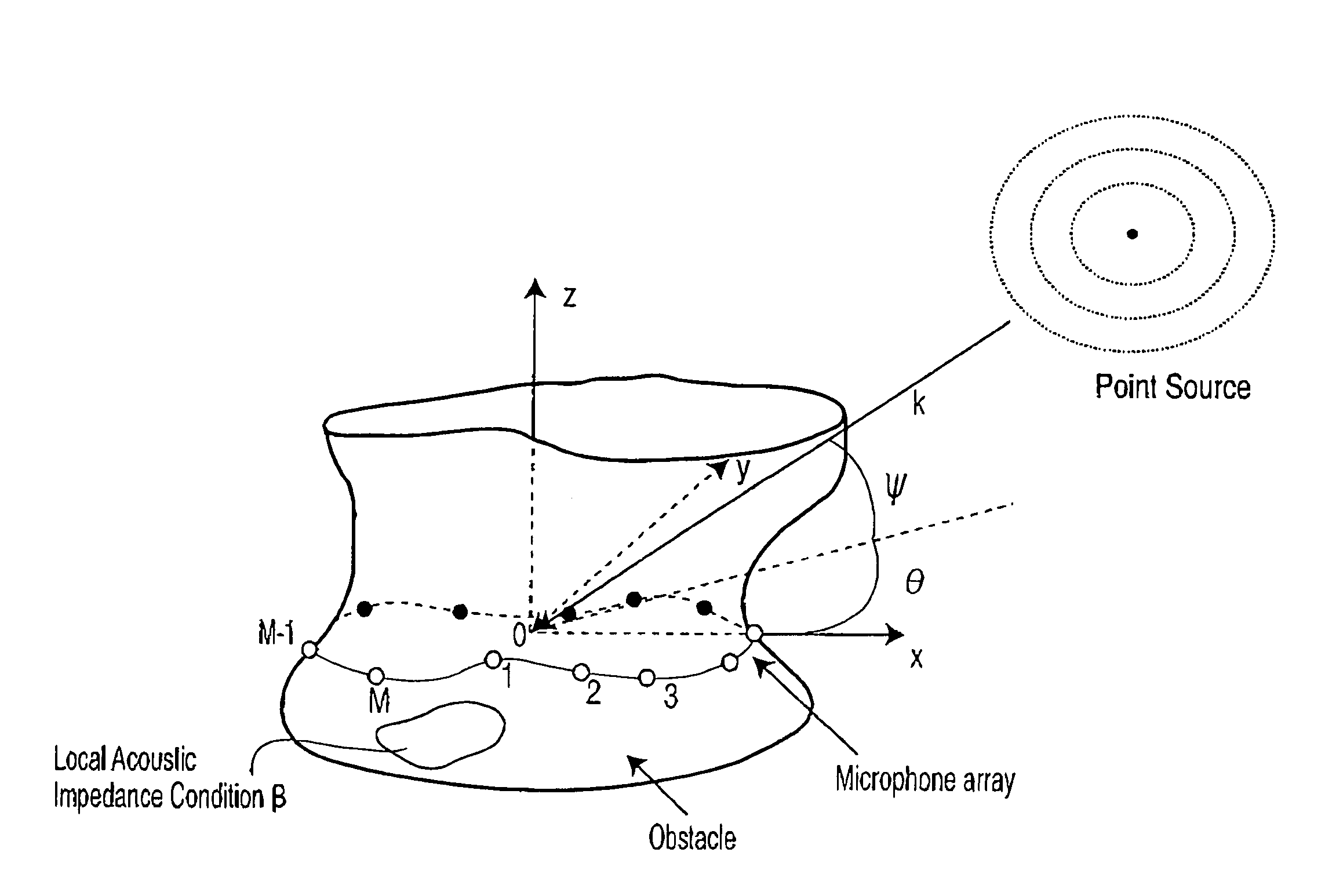
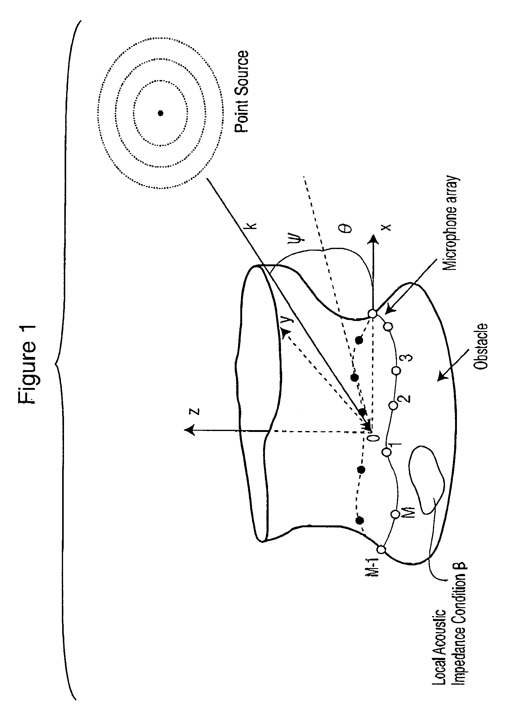
[0078]FIG. 1 shows an obstacle, which may or may not contain local acoustical treatment on the surface thereof and a sensor array of M microphones on the surface. A point source of sound is located in the k direction at an angle θ in the x-y plane and an angle ψ in the z plane...


PUM


Abstract

A method is provided for designing a broad band constant directivity beamformer for a non-linear and non-axi-symmetric sensor array embedded in an obstacle having an odd shape, where the shape is imposed by industrial design constraints. In particular, the method of the present invention provides for collecting the beam pattern and keeping the main lobe reasonably constant by combined variation of the main lobe with the look direction angle and frequency. The invention is particularly useful for microphone arrays embedded in telephone sets but can be extended to other types of sensors.

Description

FIELD OF THE INVENTION[0001]The invention relates generally to microphone arrays, and more particularly to a method for correcting the beam pattern and beamwidth of a microphone array embedded in an obstacle whose shape is not axi-symmetric.BACKGROUND OF THE INVENTION[0002]Sensor arrays are known in the art for spatially sampling wave fronts at a given frequency. The most obvious application is a microphone array embedded in a telephone set, to provide conference call functionality. In order to avoid spatial sampling aliasing, the distance, d, between sensors must be lower than λ / 2 where λ is the wavelength.[0003]Many publications are available on the subject of sensor arrays, including:[0004][1] A. Ishimaru, “Theory of unequally spaced arrays”, IRE Trans Antenna and Propagation, vol. AP-10, pp.691-702, November 1962[0005][2] Jens Meyer, “Beamforming for a circular microphone array mounted on spherically shaped objects”, Journal of the Acoustical Society of America 109 (1), January ...

Claims


Application Information

Patent Timeline
IPC IPC(8): H04R3/00H04R1/40
CPCH04R1/406H04R2201/401
Inventor DEDIEU, STEPHANEMOQUIN, PHILIPPE
Owner MITEL
Why Eureka
Try Eureka