
Secured pin entry device

Active Publication Date: 2007-09-18
TIDEL ENG LP
View PDF7 Cites 88 Cited by
  • Summary
  • Abstract
  • Description
  • Claims
  • Application Information

AI Technical Summary

Benefits of technology

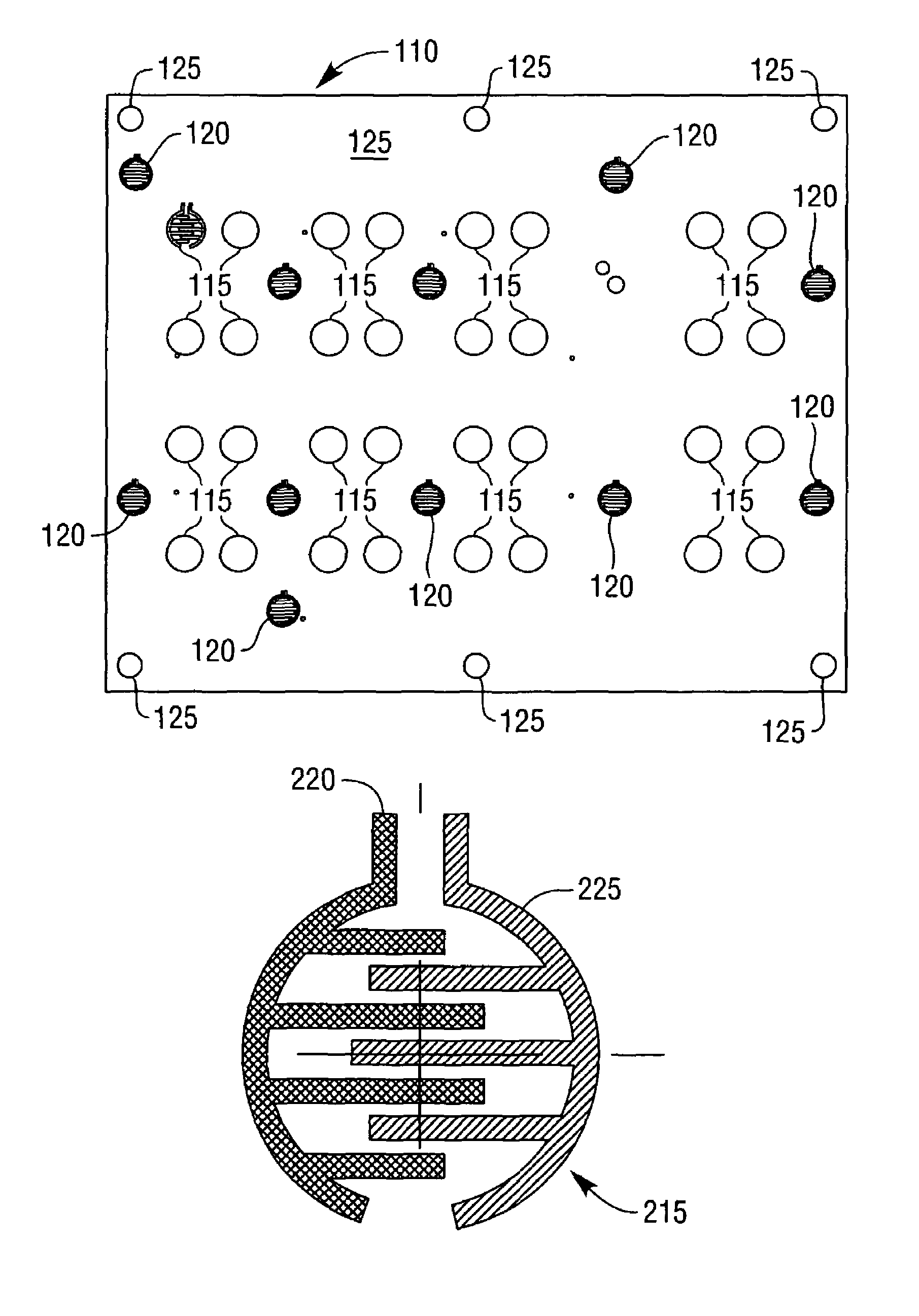
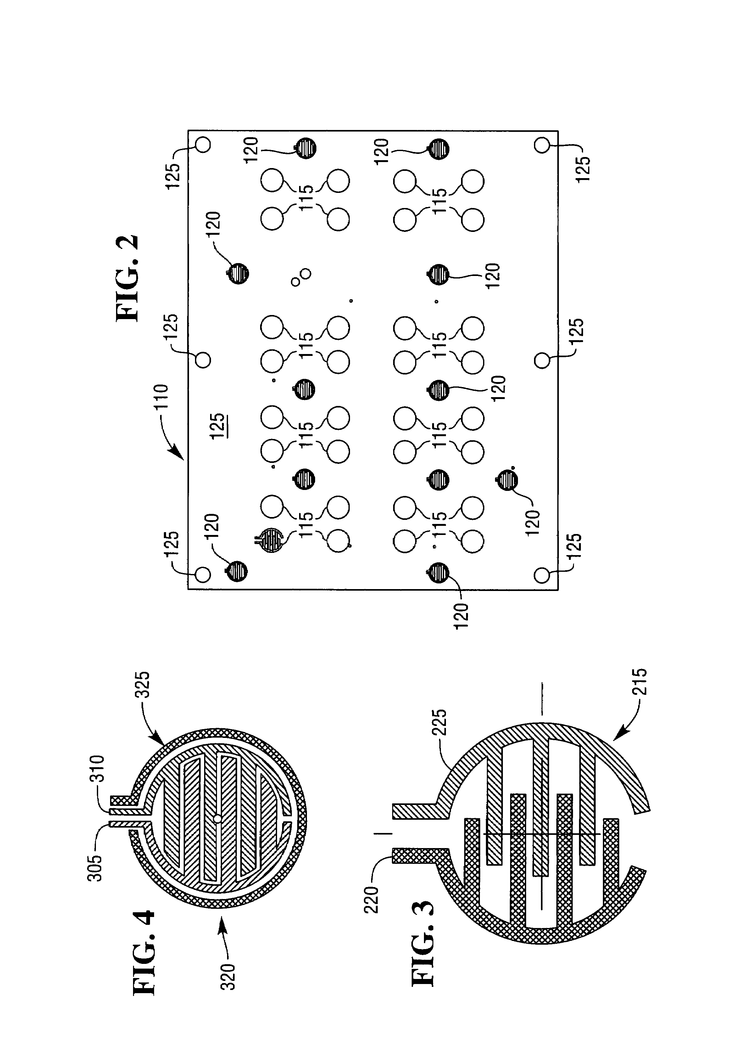
[0013]The invention is a multilayered design for a secure PED (SPED) that prevents unauthorized, undetected tampering. The front of the SPED has multiple tamper detection contacts placed throughout the sides and center of the SPED printed circuit board. Each of these tamper detection contacts is protected from injecting a conductive substance that would short the contact and bypass detecting removal of the keypad from the printed circuit board. This injection protection is a grounding contact separated by a non-conductive moat encircling the tamper detection contacts. Tamper detection circuits continually monitor the tamper detection contacts so that if the circuit's electronic signal fluctuate because of breaks or shorts, the SPED's tamper response protocol activates.

Problems solved by technology

ATMs are very reliable, but if they do malfunction typically the greatest harm to a customers is not being able to obtain cash until they can get to the bank during operating hours.
Some errors are not to the detriment of customers since there have been cases of machines giving out money without debiting the account or dispensing higher value notes because of incorrect cash denominations loaded into the money storage cassettes.
Errors that can occur may be mechanical (e.g card mechanisms, keypads, hard disk failures, memory problems, etc.); software (e.g. operating system, device driver, application, or malicious attack, etc.); communications (e.g. severed link, overload, etc); or operator error.
However, it has become increasingly obvious that many such phantom withdrawals are the result of criminal activity undertaken by sophisticated thieves exploiting vulnerabilities in the current generation of ATMs.
There have been incidents of fraud where criminals have used fake machines or have attached fake keypads or card readers to existing machines.
Past efforts to secure PINs have not been successful and banks and credit card companies are seeing increasing losses because of increasingly sophisticated ATM fraud that amounts to about $50 million a year in the U.S. alone.
These older generation PEDs can be vulnerable to taps because a cable runs from the PED to the ATM's internal encryption circuitry.

Method used


Image

  • Secured pin entry device
  • Secured pin entry device
  • Secured pin entry device

Examples


Embodiment Construction

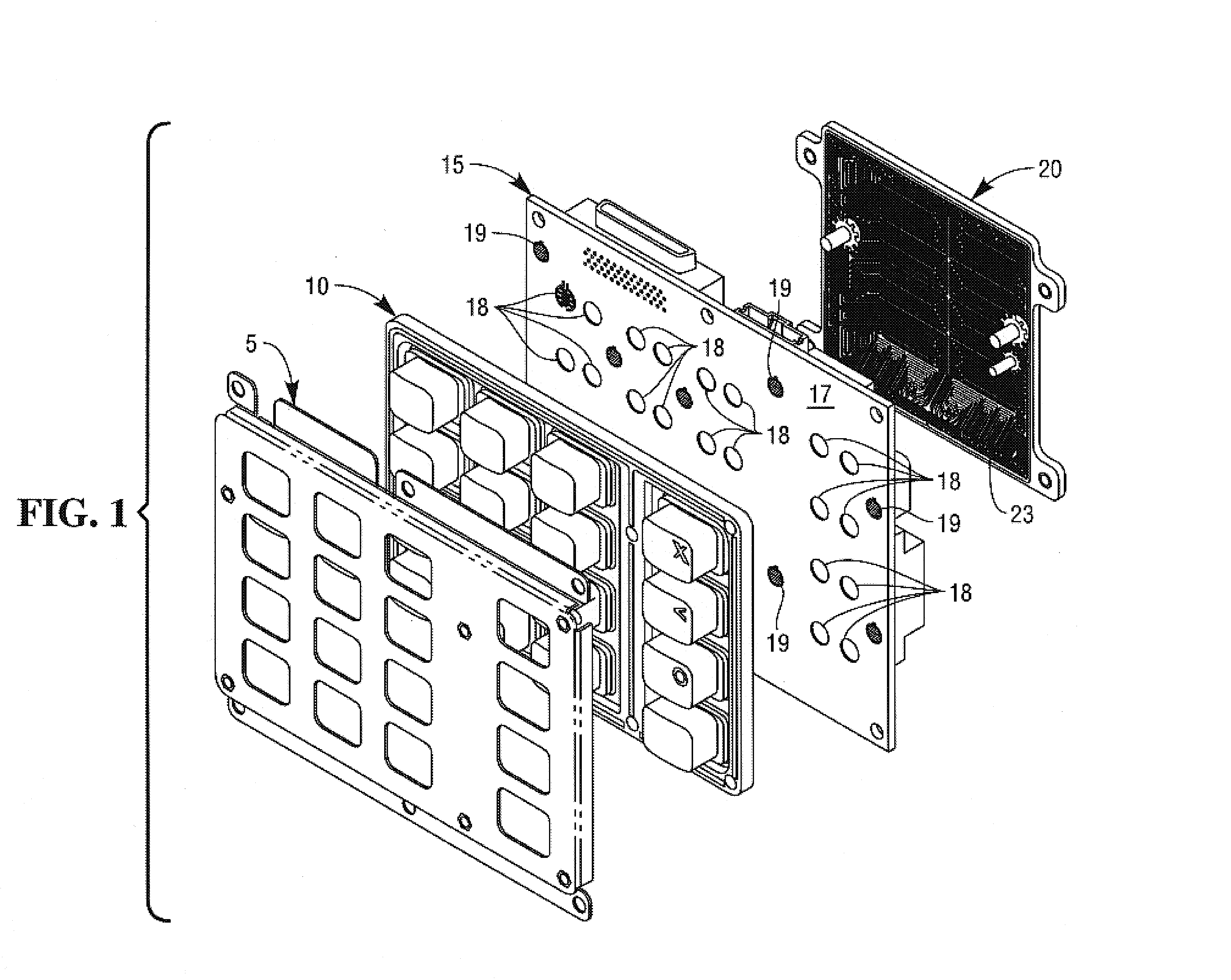
[0024]The invention is a Secure PIN Encrypting Device (SPED) used to generate an encrypted PIN (Personal Identification Number) for use over an ATM network. FIG. 1 shows the basic overall construction of the SPED and the different basic components. The SPED consists of a front keypad frame 5 that that secures a keypad 10 made of rubber or other suitable soft, waterproof, flexible material with sixteen keycaps 11. The keypad frame 5 and keypad 10 attach to the front of a printed circuit board (PCB) 15.

[0025]The PCB 15 is made from hard plastic and supports a number of electrical components. The front side of the PCB 17 includes contacts 18 registering keypad 10 depressions. The front side of the PCB 17 also includes tamper detection contacts 19 designed to detect efforts to remove the keypad cover 5 and the keypad 10. The back side of the PCB 17 includes the mounted electrical components such as connectors, a battery, and a speaker. The components also include the SPED security circu...


PUM


Abstract

The invention is a keypad for securely entering personal identification numbers onto automated teller machines (ATM) or similar devices. A frame secures a flexible keypad to a printed circuit board. The front of the circuit includes a set of tamper detection contacts whose electrical circuit is completed by conductive material on the keypad surface. A moat of conductive material surrounds the tamper detection contact. Opening the circuit by removing the keypad or shorting the circuit to the moat initiates a tamper response.Attached to the reverse side of the printed circuit board are security sensitive electrical components. These security sensitive components include a static random access memory storing cryptographic information and a crypto processor. A plastic cover imprinted with a tamper detection grid forming multiple electrical circuits coupled to a tamper detection circuit covers these components. A border of conductive material on the printed circuit board also surrounds these components. Opening or shorting any of the circuits in the grid initiates a tamper response, and shorting any of the components to the border also initiates a tamper response.

Description

TECHNICAL FIELD OF THE INVENTION[0001]A secured keypad for entering personal identification numbers on automated teller machines (ATM) or similar devices.BACKGROUND OF THE INVENTION[0002]The world's first automated teller machine (ATM) went into operation in Enfield Town, England, a borough of London, at Barclays Bank on Jun. 27, 1967. This initial ATM invention is generally credited to John Shepherd-Barron, although George Simjian registered patents in the United States in the 1930s and Don Wetzel and two other engineers from Docutel obtained a patent on an ATM on Jun. 4, 1973.[0003]In its initial and early reiterations, an ATM could only be used by customers possessing a checking or savings accounts with the bank where the ATM was located using a proprietary ATM network. By the early 1980s, banks began to take advantage of improvements in telecommunications technology to form shared ATM networks allowing customers of one bank in the network to withdraw money by using ATMs of other...

Claims


Application Information

Patent Timeline
IPC IPC(8): G06K19/06H01H3/02
CPCH01H13/702H01H2239/002H01H2239/032
Inventor MORELAND, FLYNTBUSCH, DOUGLASHOFFMASTER, JAMESPOWERS, DOUGLEVENICK, MARK
Owner TIDEL ENG LP
Learn More