Discharge device and air purifier

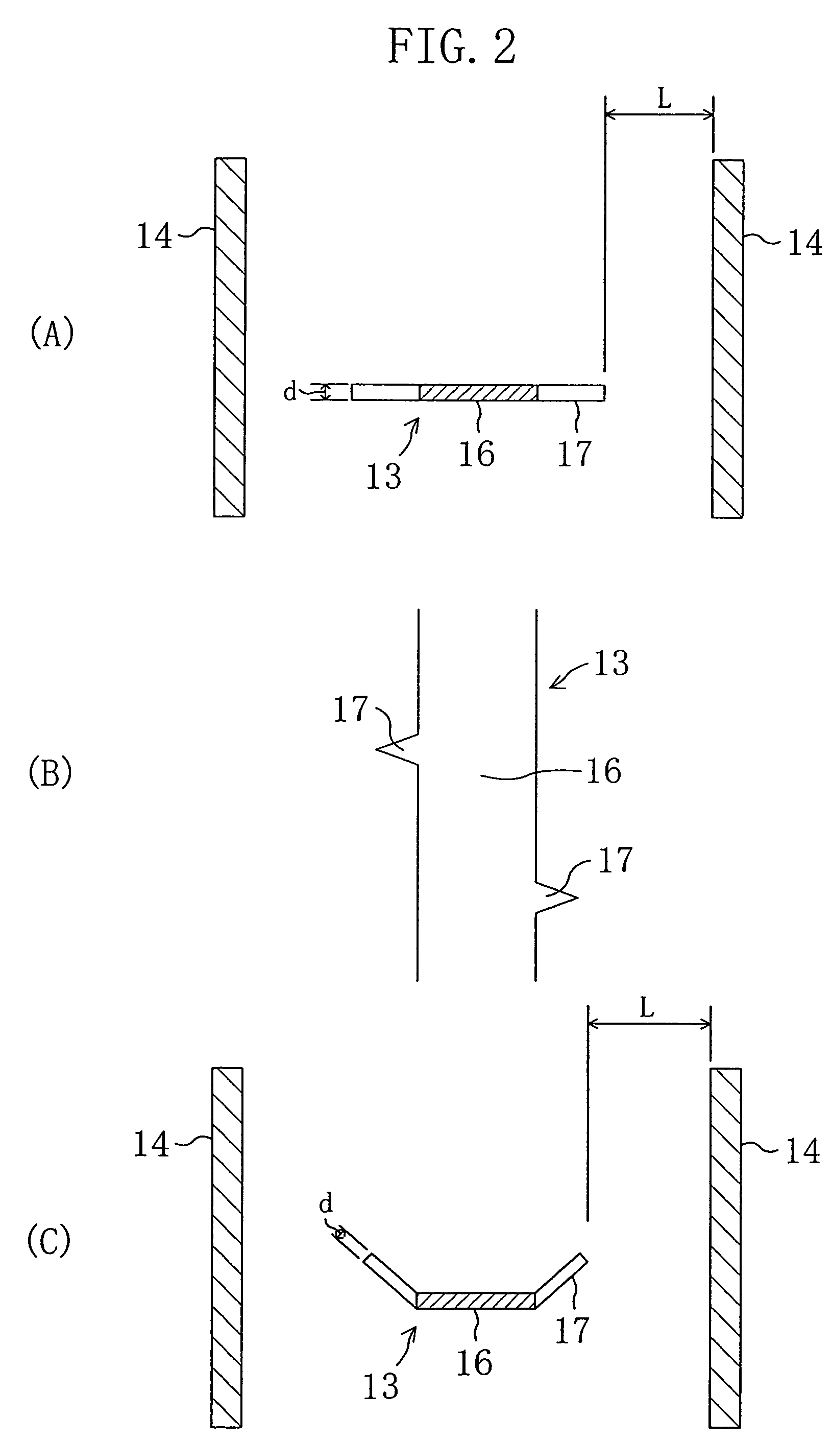
a discharge device and air purifier technology, applied in lighting and heating apparatus, electric supply techniques, heating types, etc., can solve the problems of streamer discharge making a relatively loud discharge sound, unsuitability of streamer discharge-based air purifiers, etc., to reduce the distance between the electrodes (13) and (14) and the effect of increasing the active species

Inactive Publication Date: 2007-09-18
DAIKIN IND LTD
View PDF24 Cites 19 Cited by
  • Summary
  • Abstract
  • Description
  • Claims
  • Application Information

AI Technical Summary

Benefits of technology

[0007]Under the above-described circumstances, the present invention has been achieved. An object of the present invention is to reduce noise of a discharge device which performs streamer discharge to make the discharge device applicable to consumer air purifiers, thereby improving the performance of the air purifiers.
[0008]The present invention is directed to reduce noise during streamer discharge by increasing the frequency of sound made by streamer discharge to a level higher than the frequency range which is easily perceivable by human hearing.

Problems solved by technology

However, streamer discharge makes a relatively loud discharge sound due to electrical breakdown in the air.
Therefore, the streamer discharge-based air purifier is regarded as unsuitable for places where certain silence is required such as living space and small stores.

Method used


Image

  • Discharge device and air purifier
  • Discharge device and air purifier
  • Discharge device and air purifier

Examples


embodiment 1

[0061]Hereinafter, Embodiment 1 of the present invention will be described in detail with reference to the drawings.

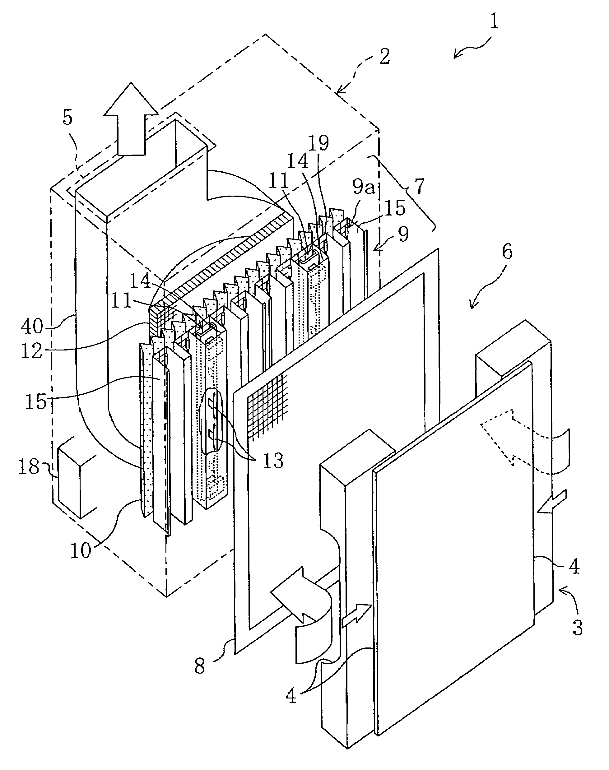
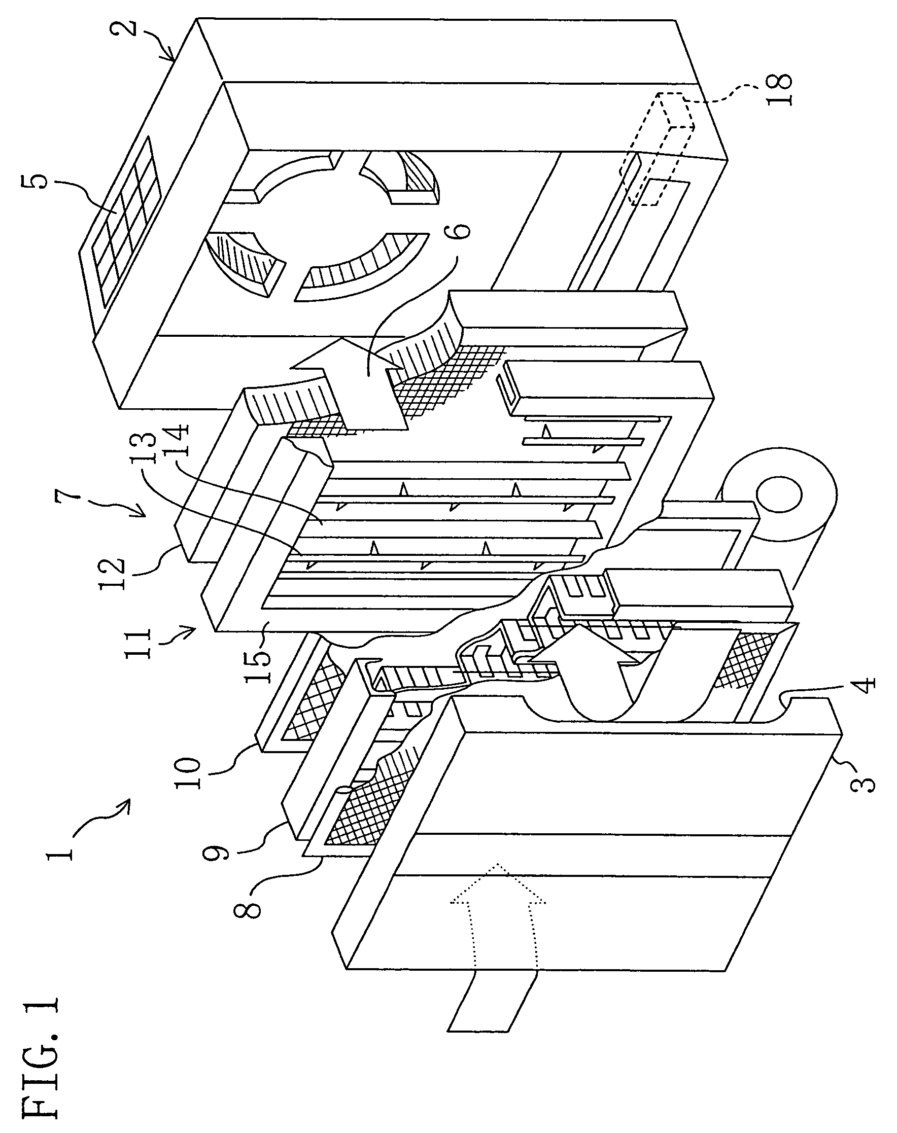
[0062]FIG. 1 is an exploded oblique view illustrating an air purifier (1) according to Embodiment 1 of the present invention. The air purifier (1) is a consumer air purifier for use at home or in small stores.

[0063]The air purifier (1) includes a box-shaped casing body (2) having an open side and a front cover (3) to be fitted to the open side. Air inlets (4) are formed on both sides of the front cover (3) to introduce a target gas into the air purifier. The casing body (2) is further provided with an air outlet (5) for emitting the target gas at the top side thereof, a fan (not shown) for circulating the target gas, a target gas flow path (6) and functional components (7) for air purification.

[0064]The functional components (7) include a prefilter (8), an ionization part (9), a dust collection filter (10), a discharge device (11) and a catalyst part (12).

[0065]The pre...

embodiment 2

[0087]Hereinafter, Embodiment 2 of the present invention will be described in detail with reference to the drawings.

[0088]FIG. 5 is an exploded oblique view illustrating an air purifier (1) according to Embodiment 2 of the present invention. FIG. 6 is a cutaway top view illustrating the inside of the air purifier (1). Similar to the air purifier of Embodiment 1, the air purifier (1) is a consumer air purifier for use at home or in small stores.

[0089]The air purifier (1) includes a box-shaped casing body (2) having an open side and a front cover (3) to be fitted to the open side. Air inlets (4) are formed on both sides and a front center part of the front cover (3) to introduce room air as a target gas into the air purifier. In a part of the top plate of the casing body (2) closer to the back side thereof, an air outlet (5) is formed to allow the room air to flow outside.

[0090]In the casing body (2), a flow path (6) for passing room air through it is provided between the air inlets (...


PUM

PropertyMeasurementUnit
distanceaaaaaaaaaa
frequencyaaaaaaaaaa
frequencyaaaaaaaaaa

Abstract

The distance between a discharge electrode and a counter electrode of a discharge device is set to not more than 10 mm such that a streamer discharge is caused between the electrodes. The frequency of sound made by the streamer discharge is raised to 6 kHz or higher to exceed the frequency range which is easily perceivable by human hearing.

Description

BACKGROUND OF THE INVENTION[0001](a) Field of the Invention[0002]The present invention relates to a discharge device which performs streamer discharge and an air purifier. In particular, it relates to a technology for reducing noise of streamer discharge.[0003](b) Background Information[0004]Air purifiers provided with discharge devices have conventionally been used as a means of decomposing and removing odorous components and hazardous components by using plasma generated by discharge. Among various discharge-based air purifiers, a streamer discharge-based air purifier is suitable for decomposition of the hazardous components and deodorization due to its high decomposition efficiency at a relatively low electric power.[0005]FIG. 8 shows a schematic configuration of a discharge device in an air purifier. The discharge device (29) includes projecting discharge electrodes (30) for generating low temperature plasma and flat counter electrodes (31) opposed to the tips of the discharge e...

Claims


Application Information

Patent Timeline
Patent Type & Authority Patents(United States)
IPC IPC(8): B03C3/40A61L9/18A61L9/22B03C3/08B03C3/32B03C3/68H01T23/00
CPCA61L9/18A61L9/22B03C3/08B03C3/32B03C3/68H01T23/00B03C2201/10A61L2209/14F24F8/192F24F8/30
Inventor TANAKA, TOSHIOKAGAWA, KENKICHIMOTEGI, KANJI
Owner DAIKIN IND LTD
Why Eureka
Try Eureka