Data transmission between a chassis and a seat movably arranged on the chassis

a data transmission and chassis technology, applied in the field of systems for transmitting data and/or energy, can solve the problems of affecting the quality of the data transmission, the inability to track the cable, and the inability to disassemble the seats, etc., and achieves the effects of low production cost, easy handling, and small overall depth of the guide rail

Inactive Publication Date: 2007-09-18
ROBERT BOSCH GMBH
View PDF1 Cites 24 Cited by
  • Summary
  • Abstract
  • Description
  • Claims
  • Application Information

AI Technical Summary

Benefits of technology

[0004]An object of the present invention is to provide a system for transmitting data and / or energy between a chassis and a seat arranged in a movable manner on the chassis, which may be produced inexpensively, is easy to handle and presents no dangers for vehicle occupants.
[0005]According to the present invention, data and / or energy is transmitted between the chassis and the seat using a transformer whose one iron-core half is positioned on a slide gliding in a guide rail, and whose other iron-core half is positioned on the seat which glides via the slide in the guide rail attached to the chassis. After the seat has been mounted on the slide, the two iron-core halves of the transformer are positioned relative to each other for the inductive data transmission and / or energy transmission, the one half of the iron core being able to glide with the slide in the guide rail during a movement of the seat. To achieve a small overall depth of the guide rail, as well as easy and inexpensive assembly, at least one primary winding of the transformer is implemented as a cable lying in the guide rail. According to the present invention, the connection for the data and / or energy transmission between the chassis and the seat results automatically when placing the seat on the slide, since in so doing, the two iron-core halves are joined. Therefore, no additional manipulation for producing the connection and no cable and plug connections are necessary.
[0006]If the cable lying in the guide rail is guided through the iron-core half arranged on the slide, this iron-core half may be closed on the side facing the guide rail, which, with the other iron-core half mounted, yields a closed ferromagnetic circuit with a low resistance of the magnetic flux in the ferromagnetic circuit. The production of the slide and the guide rail, and the mounting of the slide in the guide rail are facilitated.
[0007]To prevent the cable from bringing foreign bodies, particularly iron-containing particles, into the transformer when the seat moves, the cable is tensioned in the guide rail by a clamping device to prevent contamination of the cable with foreign bodies from the bottom of the rail and / or foreign bodies adhering to the cable are removed by a cleaning device mounted on the slide.
[0008]Production and assembly of the system may be further simplified by joining one cable end to the electroconductive guide rail and using the guide rail as a return conductor. Thus, no additional cable for the return line is necessary outside of or within the guide rail. In conjunction with the vehicle mass, the transmission system is additionally shielded from interferences.
[0009]If, to improve the reliability of the transmission system, separate primary windings are used for the data transmission and the energy transmission, the windings are advantageously combined in one cable. For shielding against electrical fields, the cable may have a coaxial construction including an inner conductor and a shield, the inner conductor being used for energy transmission and the shield being used for data transmission or vice versa. The feedback of both windings may be effected jointly via the electroconductive guide rail. With secondary windings for data transmission and energy transmission likewise separate on the seat side, it is possible to transmit data and power separately from each other.

Problems solved by technology

However, for vehicle seats, there is the problem that if the seats are mounted on rails allowing movement on the chassis of the vehicle, the cables must be tracked during a movement of the seat.
The disassembly of the seats presents another problem.

Method used


Image

  • Data transmission between a chassis and a seat movably arranged on the chassis
  • Data transmission between a chassis and a seat movably arranged on the chassis
  • Data transmission between a chassis and a seat movably arranged on the chassis

Examples


Embodiment Construction

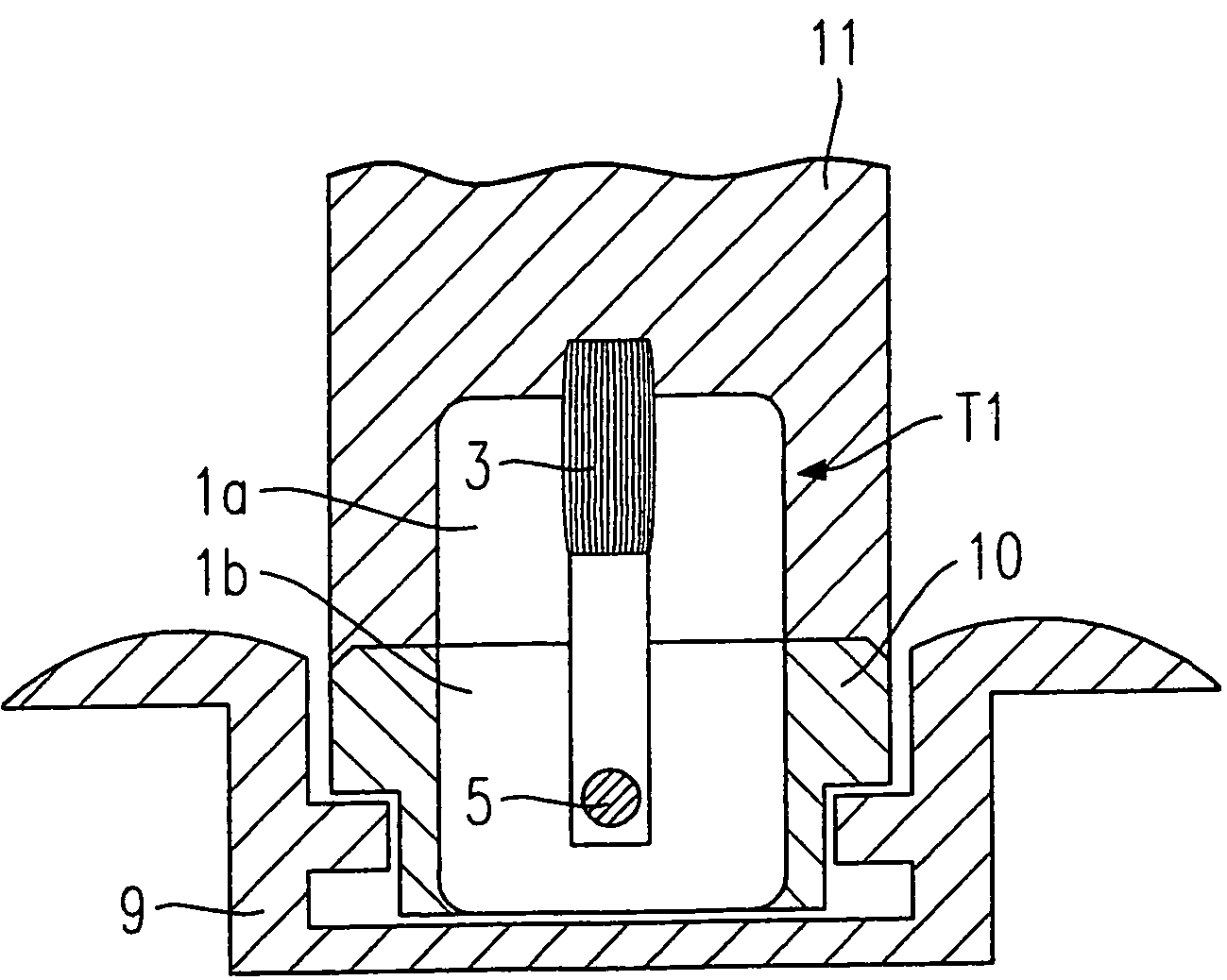
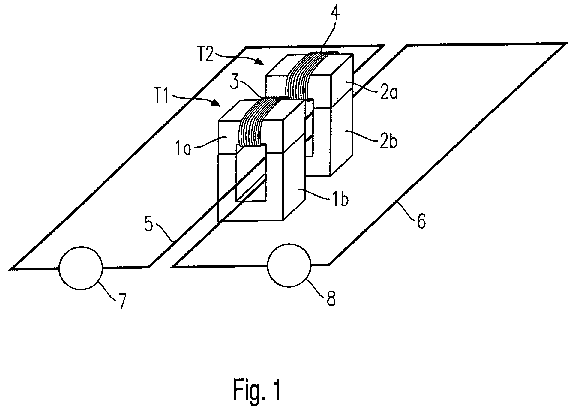
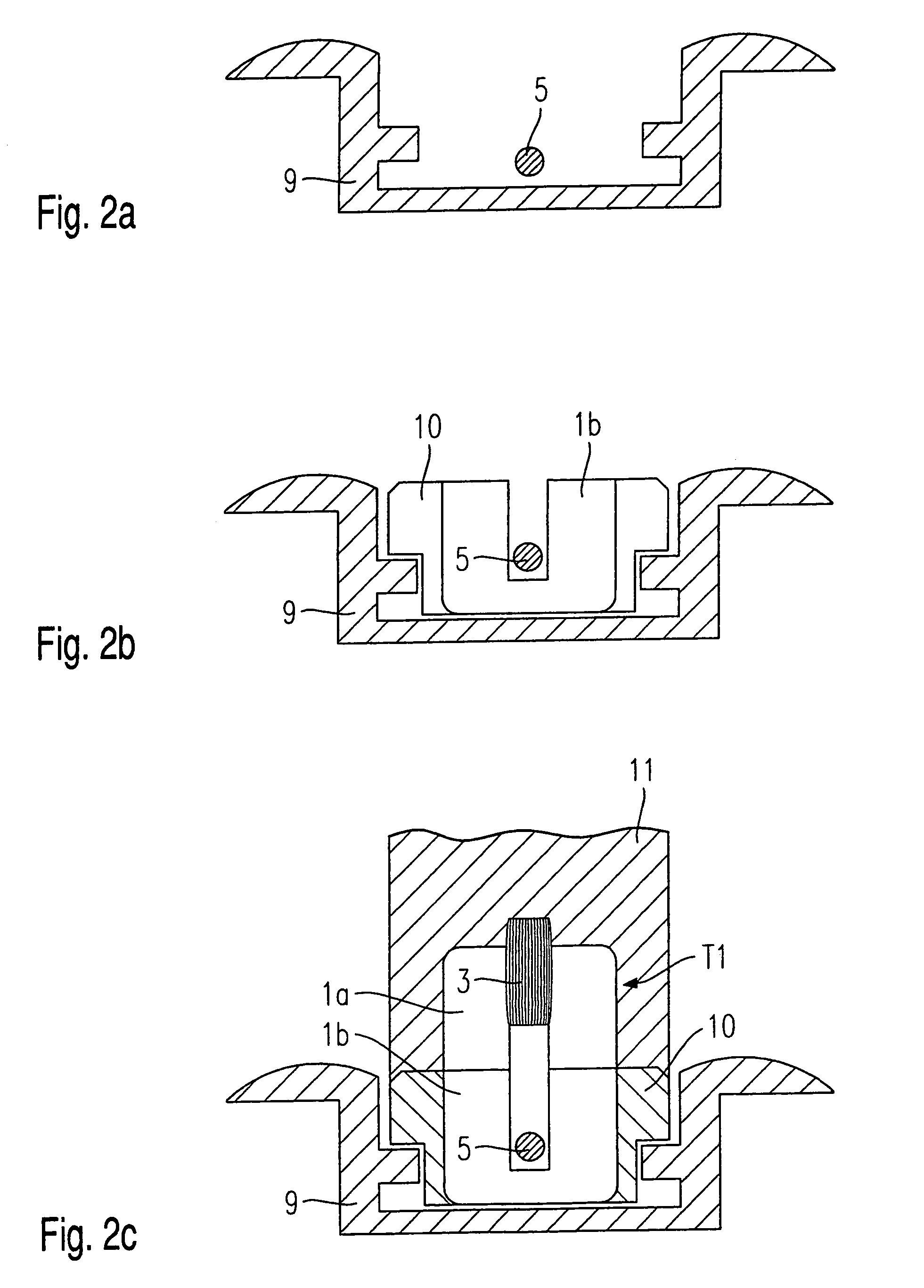
[0015]According to the present invention, the data is transmitted in a cable-less manner at the interface between the seat and the chassis using an inductive connection. Existing cable connections may easily be replaced by the system of the present invention without having to change the existing data-transmission system of the vehicle. It may only be necessary to provide amplifiers on the seat side and / or the chassis side which condition, amplify and feed the signals to be transmitted or received into the bus system on the chassis side.

[0016]If no energy source is provided on the seat side for powering sensors or an amplifier, the needed energy (e.g. 5 watts) may likewise be transmitted from the chassis via the inductive connection to the seat; the data signal to be transmitted may be modulated upon the energy-carrier wave. For a reciprocal data transmission between the seat and the chassis, it may be advantageous to provide separate primary and / or secondary windings on the transfor...


PUM


Abstract

A system for transmitting data and / or energy between a chassis and a seat movably arranged on the chassis, the seat being able to glide in guide rails, attached to the chassis, with the aid of slides; one iron-core half of a transformer—the iron-core half bearing at least one primary winding—is disposed on the slide gliding in the guide rail, the primary winding being a cable lying in the guide rail; and the other iron-core half of the transformer having a secondary winding is arranged on the seat, the two iron-core halves of the transformer being positioned relative to each other for the data and / or energy transmission when the seat is mounted.

Description

FIELD OF THE INVENTION[0001]The present invention relates to a system for transmitting data and / or energy between a chassis and a seat arranged in a movable manner on the chassis, the seat being able to glide with the aid of slides in guide rails attached to the chassis.BACKGROUND INFORMATION[0002]To increase the safety of vehicle occupants, more and more functions are being integrated into the seats of vehicles, these functions being controlled and monitored electronically on the chassis side. Among these functions, in addition to the monitoring and triggering of airbags integrated in the seats, are also queries concerning seat occupancy and seat belt buckles, as well as child-seat detection for the optimal triggering of occupant restraint systems.[0003]In general, data is transmitted in vehicles by bus systems via cable. This type of data transmission has proven itself. However, for vehicle seats, there is the problem that if the seats are mounted on rails allowing movement on the...

Claims


Application Information

Patent Timeline
Patent Type & Authority Patents(United States)
IPC IPC(8): B60L1/00B60L3/00H02G3/00G08C17/00H02J17/00H04B5/00
CPCG08C19/06
Inventor DUKART, ANTONKAZMIERCZAK, HARALD
Owner ROBERT BOSCH GMBH
Why Eureka
Try Eureka