Vehicle electrical assist apparatus and kit for same

a technology for electrical assistance and vehicles, applied in the direction of motor/generator/converter stopper, dynamo-electric converter control, instruments, etc., can solve the problems of increasing the efficiency of internal combustion engines, reducing carrying capacity, and reluctant to give up performance, so as to increase fuel economy and achieve the effect of not reducing performan

Active Publication Date: 2007-09-18
CICCONE GABRIEL
View PDF19 Cites 46 Cited by
  • Summary
  • Abstract
  • Description
  • Claims
  • Application Information

AI Technical Summary

Benefits of technology

[0008]It is an object of the invention to provide an electrical assist apparatus for a motor vehicle that increases fuel economy during selected driving conditions, without decreasing performance.

Problems solved by technology

Generally, there have been a variety of technologies that have been developed that result in incremental increases in efficiencies of internal combustion engines.
However, experience has shown that many consumers are generally reluctant to give up performance and to drastically reduce carrying capacity in order to save on energy costs.
However, these vehicles tend to be small, sometime have limited range when operating on the electric motors, and demand a premium in cost.
Further, it is necessary to replace the batteries during the life of the vehicle, thus further increasing cost.
This has limited the desirability of such vehicles to owners who are willing to make sacrifices in performance and load handling capability, and do enough driving to justify the increase cost, even after tax advantages that may be associated with the purchase of such motor vehicles.
Another difficulty with such prior art technologies is that they are not applicable to the existing vehicles that are already on the road.
There are many vehicle owners who would be very pleased to have a technology to boost fuel economy, but who have functional vehicles, and are not yet ready to go to the considerable expense of purchasing a new vehicle.

Method used


Image

  • Vehicle electrical assist apparatus and kit for same
  • Vehicle electrical assist apparatus and kit for same
  • Vehicle electrical assist apparatus and kit for same

Examples


Embodiment Construction

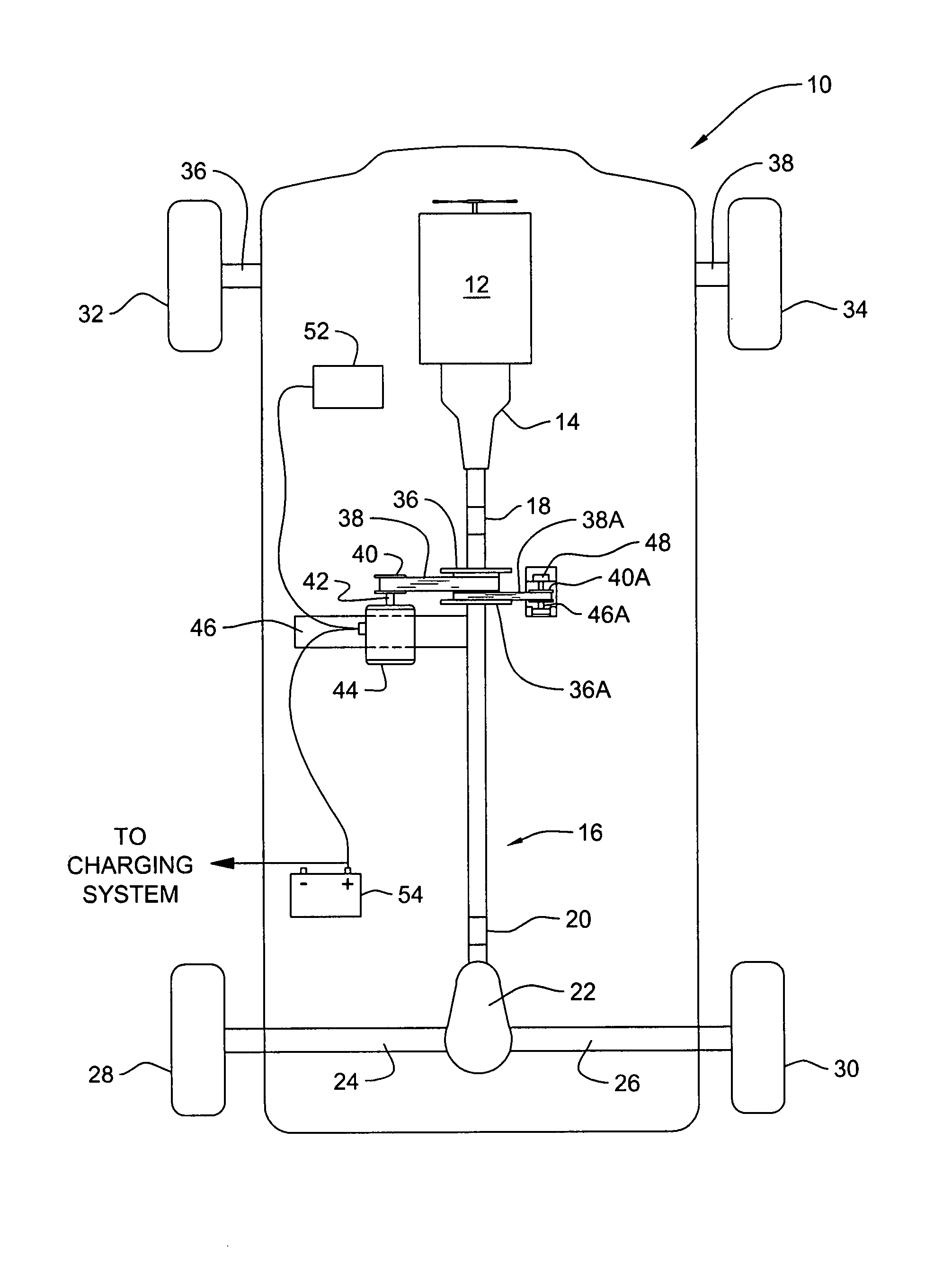
[0024]Referring to FIG. 1, there is shown a bottom view of a motor vehicle 10 incorporating features of the present invention. Although the present invention will be described with reference to the embodiments shown in the drawings, it should be understood that the present invention can be embodied in many alternate forms of embodiments. In addition, any suitable size, shape or type of elements or materials could be used.

[0025]Motor vehicle 10 may be any of several types of vehicles such as a simple automobile or car, a sports utility vehicle, or a truck. Vehicle 10 may be configured with a conventional internal combustion engine 12, a transmission 14, and a drive shaft assembly 16 that is caused to rotate by the transmission. Drive shaft assembly 16 may have universal joints 18 and 20 along its length, as is well known in the art. The end of drive shaft assembly 16 remote from transmission 14 is connected to a differential gear assembly 22, which serves to rotate drive shafts withi...


PUM


Abstract

Apparatus for installation in new motor vehicles or for retrofitting into existing motor vehicles, including an electric motor coupled to a drive shaft and a controller for the motor. The existing vehicle battery and/or an auxiliary storage battery can be used to power the motor to drive the vehicle during certain driving conditions, resulting in greatly increased fuel economy, without interfering with the normal performance of the vehicle. A kit of parts may be provided for simple and economical installation on existing vehicles. A motor vehicle so equipped.

Description

[0001]This application claims priority, under 35 U.S.C. §119(e), from U.S. provisional application Ser. No. 60 / 649,741 filed on Feb. 3, 2005; and the entire teachings of that application is hereby incorporated by reference, in its entirety. Reference is also made to Disclosure Document 560652 filed with the United States Patent and Trademark Office on Sep. 15, 2004. It is requested that Disclosure Document 560652 be transferred into the file of the present application.BACKGROUND OF THE INVENTION[0002]1. Field of the Invention[0003]The present invention relates to apparatus for increasing the mileage of motor vehicles. More particularly, it relates to those apparatus that utilize electrical energy storage and an electrical motor to lower overall energy consumption of a motor vehicle.[0004]2. Background Art[0005]As the cost of hydrocarbon fuels, and in particular the cost of gasoline and diesel fuel have increased, there it has become increasingly desirable to develop technologies tha...

Claims


Application Information

Patent Timeline
Patent Type & Authority Patents(United States)
IPC IPC(8): H02P3/00
CPCB60K6/365B60K6/485B60W10/08B60L2240/421B60W20/00B60W2510/081B60W2520/10B60W2710/081Y02T10/6226Y02T10/642Y02T10/62Y02T10/64B60W10/26
Inventor CICCONE, GABRIEL
Owner CICCONE GABRIEL
Why Eureka
Try Eureka