
Probe head for nuclear magnetic resonance measurements

a technology of nuclear magnetic resonance and probe head, which is applied in the direction of magnetic measurement, geological measurement, reradiation, etc., can solve the problems of large dimensions, complex apparatuses which are difficult to operate, and relatively limited sensitivity and spatial resolution, and achieve simple operation, robust design, and low cost

Active Publication Date: 2007-09-18
BRUKER BIOSPIN
View PDF7 Cites 11 Cited by
  • Summary
  • Abstract
  • Description
  • Claims
  • Application Information

AI Technical Summary

Benefits of technology

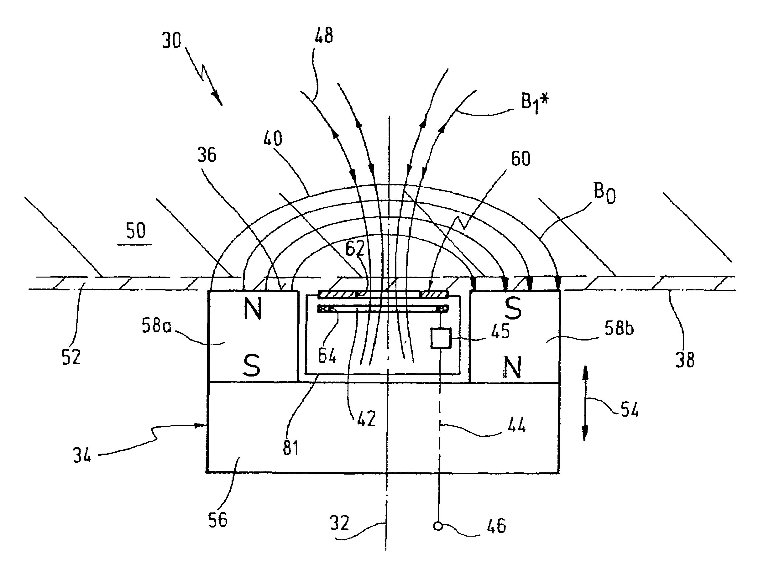
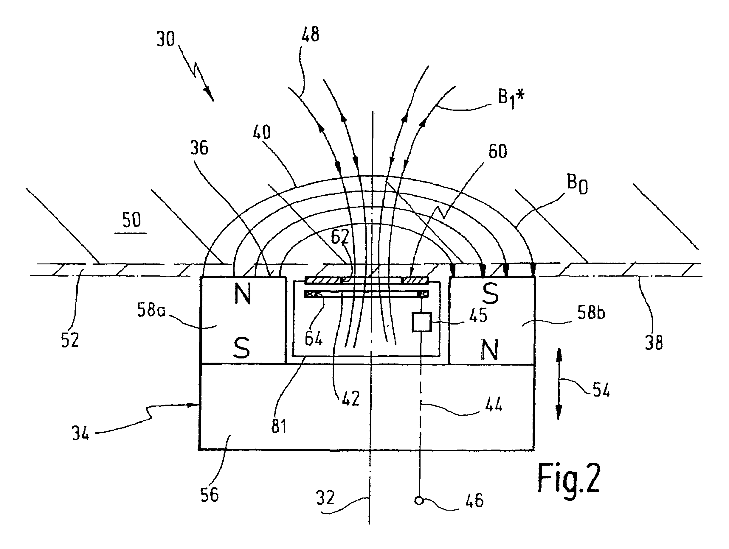
The present invention provides a probe head for nuclear magnetic resonance measurements in the area of a surface of a measuring object. The probe head has a simple and flat design, is robust, and can be manufactured at low cost. The design includes a first means for generating a static magnetic field, a second means for generating a radio frequency magnetic field, and a third means for amplifying the radio frequency magnetic field. The third means is a small aperture located between the second means and the surface of the object. The design can be easily adapted to different requirements and can be used with different second and third means for different applications. The technical effects of the invention are improved accuracy and precision of magnetic resonance measurements, reduced eddy currents, and a simplified and cost-effective design.

Problems solved by technology

Conventional apparatuses of this kind are characterized by their relatively limited sensitivity and their limited spatial resolution.
This approach, however, requires substantial design efforts and results in complex apparatuses which are difficult to operate and are, for example, inappropriate for mobile applications.
This prior art apparatus has the disadvantage that it is complex in its design and has large dimensions.
Mobile field applications, in particular under confined spatial circumstances, are impossible.

Method used


Image

  • Probe head for nuclear magnetic resonance measurements
  • Probe head for nuclear magnetic resonance measurements
  • Probe head for nuclear magnetic resonance measurements

Examples


Embodiment Construction

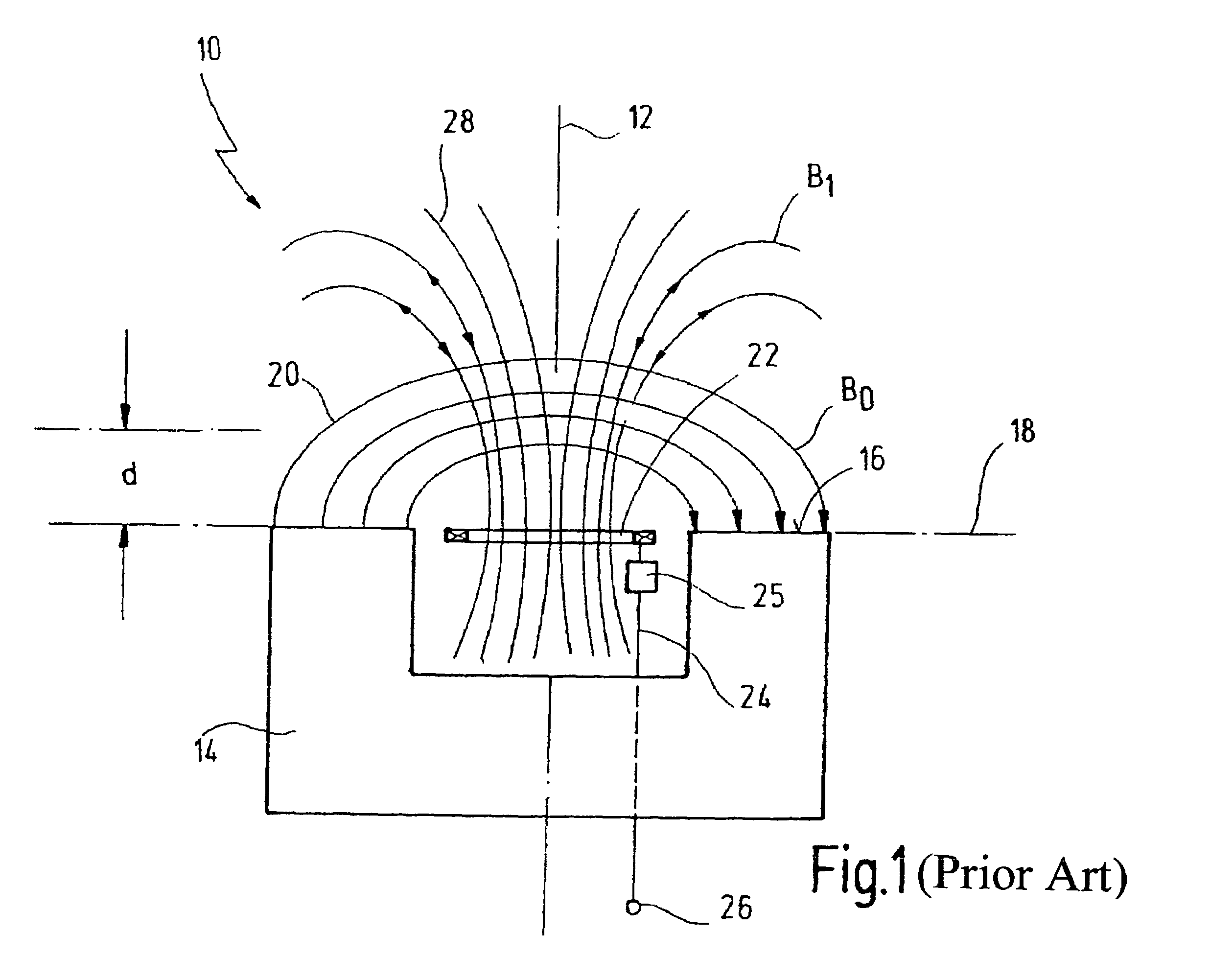
[0046]In FIG. 1 reference numeral 10 as a whole designates a probe head for measurements close to the surface by means of NMR, according to the prior art. A U-shaped magnet system 14 is provided symmetrically to an axis 12. Magnet system 14 has legs having free surfaces which configure contact surfaces 16 of probe head 10. Probe head 10 may be applied with these contact surfaces 16 on a surface 18 of a measuring object, with surface 18 extending perpendicular to axis 12.

[0047]Field lines 20 of the constant magnetic field B0 generated by magnet system 14 exit under right angles from contact surfaces 16, and bridge the gap between the legs with an arc. In the area of axis 12 the extend perpendicular to the latter.

[0048]A radio frequency coil 22 is located between the legs of magnet system 14 in the area of axis 12. Radio frequency coil 22 is connected to a terminal 26 via a line 24 and a matching and tuning unit 25. Radio frequency coil 24 is positioned such that field lines 28 of a r...


PUM


Abstract

A probe head for nuclear magnetic resonance measurements in an area of a surface of a measuring object is disclosed. The probe head comprises first means for generating a static magnetic field extending at least partially parallel to the surface, second means for generating a radio frequency magnetic field having components extending perpendicular to the surface, and third means for amplifying a radio frequency magnetic field effective within the measuring object. The third means are configured as an aperture and are located between the second means and the surface.

Description

FIELD OF THE INVENTION[0001]The invention, generally, is related to the field of nuclear magnetic resonance (NMR) measurements.[0002]More specifically, the invention is related to the field of probe heads for such measurements, in particular to the field of so-called surface coil probe heads.[0003]Still more specifically, the invention is related to a probe head for nuclear magnetic resonance measurements in the area of a surface of a measuring object, comprising first means for generating a static magnetic field extending at least partially parallel to the surface, second means for generating a radio frequency magnetic field having components extending perpendicular to the surface, and third means for amplifying the radio frequency magnetic field effective within the measuring object.BACKGROUND OF THE INVENTION[0004]For investigating areas of objects which are close to the object's surface it is well known in the art of NMR to use so-called surface coils. An example for such a coil...

Claims


Application Information

Patent Timeline
Patent Type & Authority Patents(United States)
IPC IPC(8): G01V3/00
CPCG01R33/341G01R33/3808G01R33/422G01N24/081G01R33/34007
Inventor MELZI, ROBERTOTEDOLDI, FABIOBIZZARO, GIOVANNI
Owner BRUKER BIOSPIN
Learn More