Ridge waveguide with recess

Active Publication Date: 2007-09-18
SEAGATE TECH LLC
View PDF34 Cites 30 Cited by
  • Summary
  • Abstract
  • Description
  • Claims
  • Application Information

AI Technical Summary

Benefits of technology

[0016]The invention comprises forming a recess in the ridge of a ridge waveguide at its terminal portion to space the ridge from the walls of the waveguide's aperture. The recessed ridge forms a tip at the end of the waveguide facing the media. The recessed ridge waveguide concentrates the electric field of light propagating in the ridge waveguide at the tip. The recess prevents th

Problems solved by technology

One of the difficulties with the technique is finding a method to heat just the small area which is to be recorded.
Heating with laser light as is done in magneto-optic recording is the most promising approach, but the difficulty with this is that at the current storage densities contemplated for HAMR, the spot to be hea

Method used


Image

  • Ridge waveguide with recess
  • Ridge waveguide with recess
  • Ridge waveguide with recess

Examples


Embodiment Construction

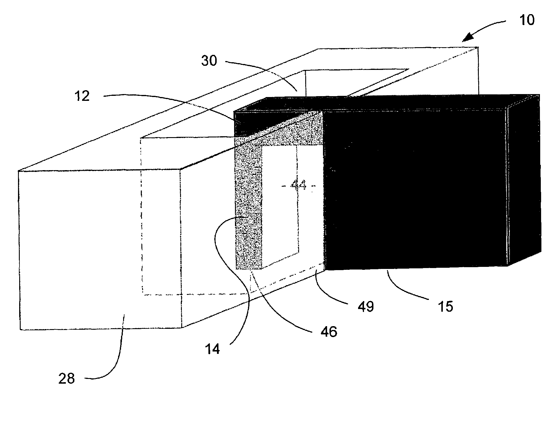
[0032]FIG. 3 illustrates a top plan view of the inventive waveguide structure 40. The waveguide 40 includes a “C”-shaped aperture 30 formed within a waveguide body structure 28. The body 28 of the waveguide 40 is composed of a highly conductive material such as gold, silver, copper or aluminum. Aperture 30 is formed by a pair of elongated walls 27 and 29, a pair of side walls 25 and a central ridge 12 extending into aperture 30 from one 27 of the elongated walls. The ridge 12 has a terminal wall 26 facing the opposite 29 elongated walls.

[0033]FIG. 4 is a cross-section taken along 4-4 of FIG. 3. It illustrates a side cross-sectional view of the ridge waveguide 40 closely spaced from a recording medium 42. A beam of light may be focused on the top surface 60 of the waveguide 40. Light from the beam travels through the aperture 30 and exits the aperture 30 at a terminal end 48 of the aperture 30 at the bottom surface 62 of the waveguide 40. The light energy then spreads between the bot...


PUM


Abstract

A ridge waveguide having a recessed ridge forming an isolated tip at a terminal end of the waveguide's aperture efficiently couples light into a spot adjacent to the tip in a medium below the terminal end of the waveguide which is significantly smaller than the light's wavelength. The waveguide is used to heat a recording medium via the small spot for heat assisted recording or to pattern substrates by photolithography with line width exposures that are significantly smaller than the wavelength of light. The body of the waveguide may also be recessed away from the medium in an area surrounding the waveguide's aperture to further confine the energy emerging from the waveguide to the small spot adjacent the tip in the medium.

Description

CROSS-REFERENCE TO RELATED APPLICATIONS[0001]This application claims benefit of U.S. provisional patent application Ser. No. 60 / 368,909, filed on Mar. 29, 2002, which is hereby incorporated by reference.GOVERNMENT RIGHTS[0002]This invention was made with United States Government support under Agreement No. 70NANB1H3056 awarded by the National Institute of Standards and Technology (NIST).[0003]The United States Government has certain rights in the invention.BACKGROUND OF THE INVENTION[0004]1. Field of the Invention[0005]The invention relates to waveguides in general and more particularly to heat assisted recording. It also relates to near field microscopy and to nanoscale photolithography.[0006]2. Description of the Related Art[0007]Heat-assisted magnetic recording (HAMR) involves heating a spot on the surface of a magnetic recording medium to reduce its coercivity sufficiently so that it can be magnetically recorded by an applied recording field. The advantage of this technique is t...

Claims


Application Information

Patent Timeline
IPC IPC(8): G11B7/00G02B6/12G03F7/20G11B5/127G11B7/135G11B11/105
CPCB82Y10/00B82Y20/00G02B6/12G03F7/70383G11B5/127G11B7/1387G11B11/10536G11B2005/0021G11B5/6088
Inventor CHALLENER, WILLIAM ALBERT
Owner SEAGATE TECH LLC
Why Eureka
Try Eureka