Cooling apparatus for heat generating devices

a technology of heat generation device and cooling apparatus, which is applied in the direction of electrical apparatus casing/cabinet/drawer, lighting and heating apparatus, domestic stoves or ranges, etc., can solve the problems of lowering acoustic noise and a large arrangement, and achieve the effect of enhancing cooling efficiency

Inactive Publication Date: 2007-09-25
GOOGLE LLC
View PDF16 Cites 42 Cited by
  • Summary
  • Abstract
  • Description
  • Claims
  • Application Information

AI Technical Summary

Benefits of technology

[0008]The apparatus includes a plurality of parallel disks that rotate at the center of a set of heat transfer fins and periodic radial elements placed between disks to generate air flow more efficiently while maintaining the air stream less turbulent. The air leaving the edge of the parallel disks as the disks rotate is more easily directed into the surrounding heat transfer fins. This arrangement of rotating disks creates air flow more efficiently. Furthermore, an array of heat pipes carrying heat from the source to the rotating disks increases the surface area of heat dissipation, leading to more efficient cooling. Additionally provided is a mechanism of transferring heat from a heat generating device to the rotating disks.
[0011]Still in a further embodiment, the plurality of disk fan elements may be mounted on a hollow shaft whereby a motor drive means for rotating the shaft is integrated in the shaft. Further, the hollow shaft is configured to include a plurality of air slots located along a length of the shaft for permitting air to pass through the shaft as the shaft rotates and exit the formed air gaps. Thus, further cooling efficiency is enhanced as heat is dissipated through the parallel disks of the fan.

Problems solved by technology

Current known cooling solutions have drawbacks in providing an adequate cooling to chips in small spaces and, drawbacks in lowering acoustic noise.
The arrangement is rather bulky, however, with only a small portion of a disk pumping air at any given time.

Method used


Image

  • Cooling apparatus for heat generating devices
  • Cooling apparatus for heat generating devices
  • Cooling apparatus for heat generating devices

Examples


Embodiment Construction

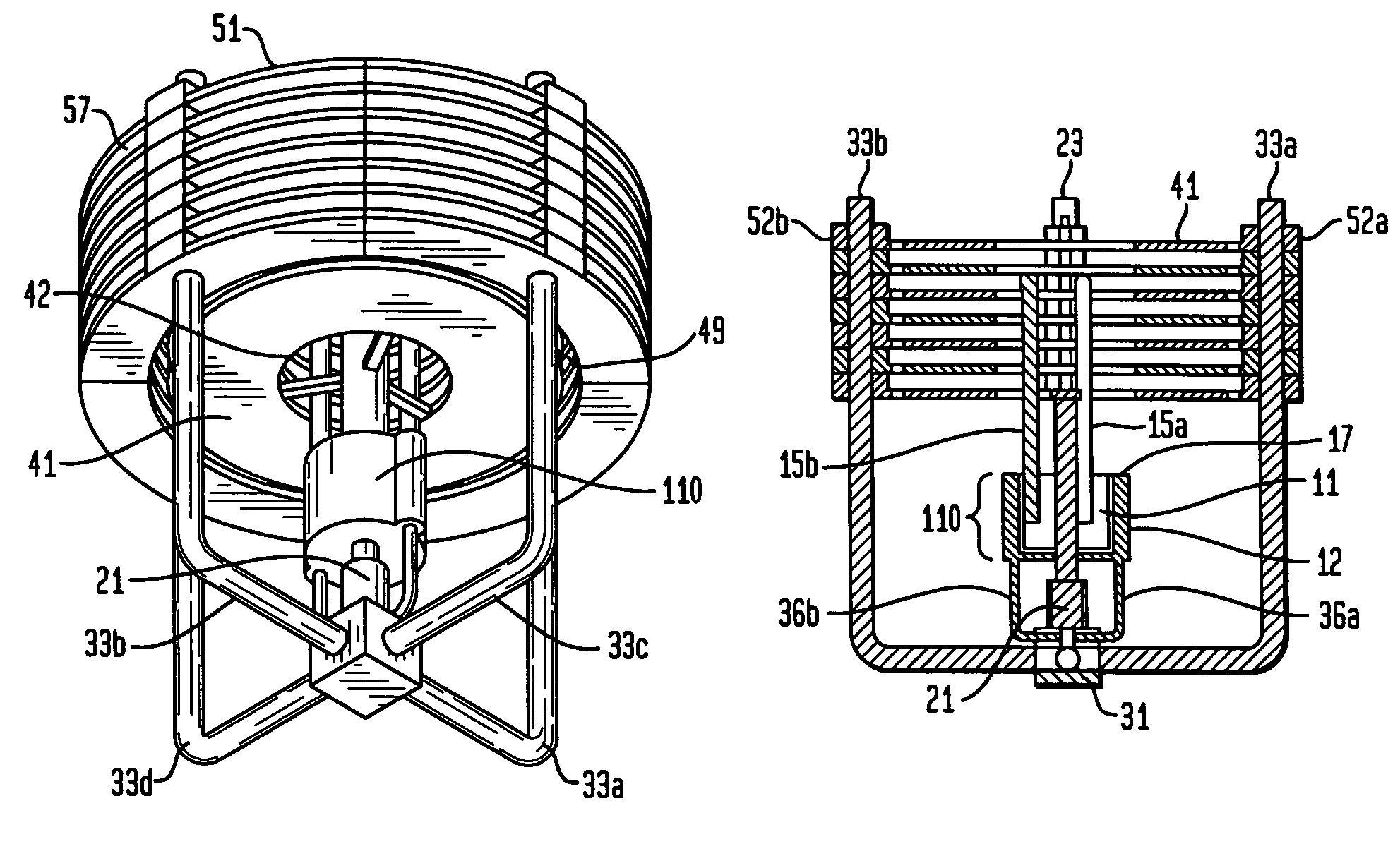
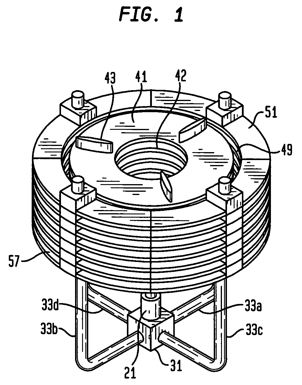
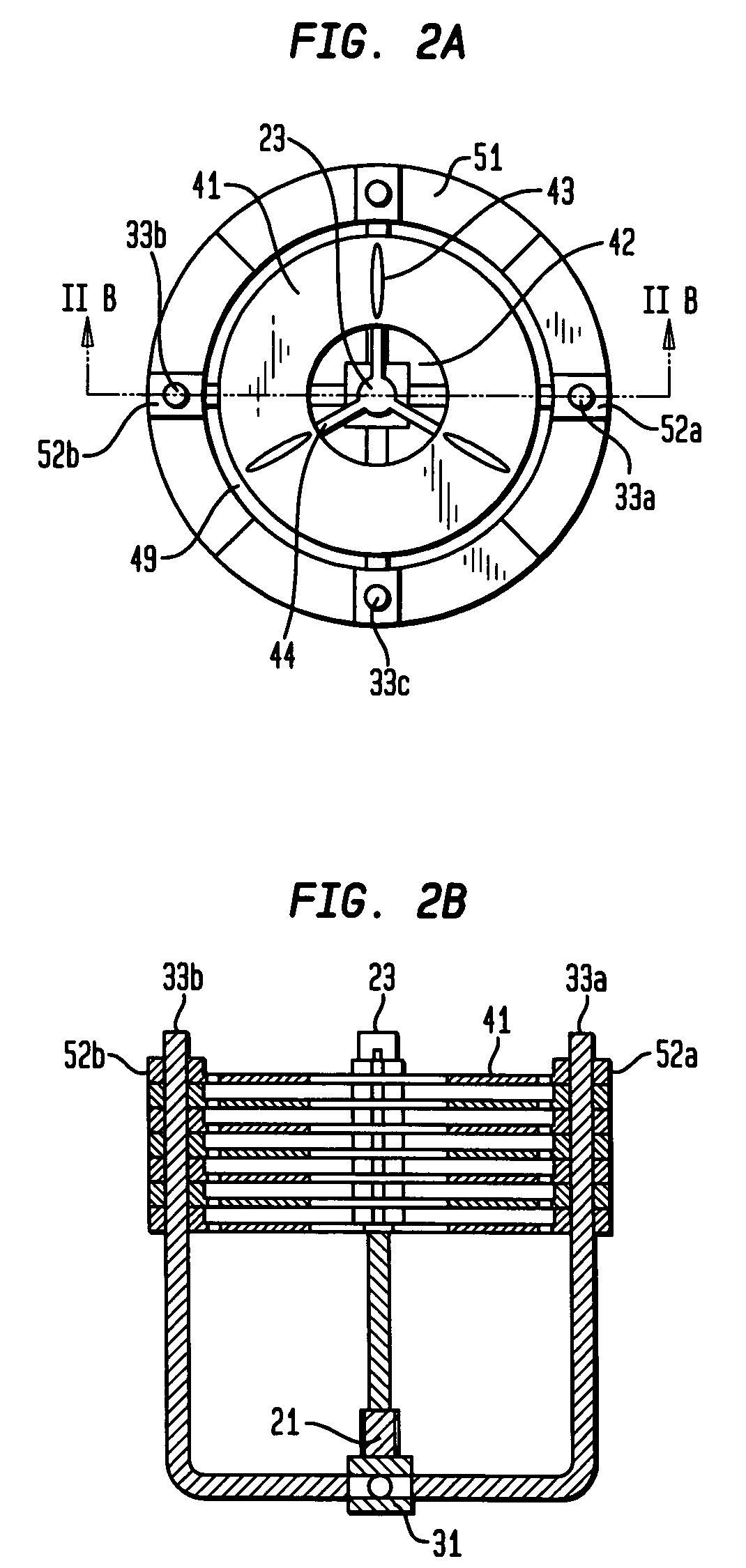
[0020]FIG. 1 depicts generally, the cooling device of the present invention. As shown in FIG. 1, the cooling device includes a plurality of ring-shaped heat sink fins 51 oriented parallel in a stacked configuration with a gap 57 between each ring-shaped heat sink fin, a plurality of circular disk fans 41 oriented parallel in a stacked configuration and coaxial with the plurality of ring-shaped heat sink fins 51, the plurality of stacked circular disk fans 41 being mounted for rotation within the stacked plurality of circular heat sink fins 51 via a shaft under motor control 21. As shown in FIG. 1, and described in greater detail herein, the plurality of heat sink fins 51 are in communication with a structure comprising heating pipe elements 33a, . . . , 33d interconnected with a heat distribution block 31 that receives and distributes heat generated by a semiconductor chip to the heat sink fins. Preferably, as shown in FIG. 1, the parallel circular disk fans 41 each include radial e...


PUM


Abstract

A cooling apparatus for heat generating devices such as semiconductor chips comprises a parallel disk fan in the middle of a set of heat sink fins. The parallel disk fan has radial elements placed between the disks to efficiently create air flow without turbulence. Cooling efficiency is further enhanced when heat dissipation through the parallel disks of the fan is introduced.

Description

BACKGROUND OF THE INVENTION[0001]1. Field of the Invention[0002]The present invention relates generally to cooling devices for devices that generate heat such as semiconductor chips, and particularly, to an apparatus that improves the capability and reliability of cooling devices for semiconductor chips. The invention is in the field of heat transfer and cooling of semiconductor chips used in computers and telecommunication equipment.[0003]2. Description of the Prior Art[0004]As the power of semiconductor chips increases, more efficient cooling device for semiconductor chips is therefore required. Current known cooling solutions have drawbacks in providing an adequate cooling to chips in small spaces and, drawbacks in lowering acoustic noise. For instance, U.S. Pat. Nos. 5,297,617, 5,309,983, and 5,445,215 each describe methods of using miniature “muffin fans” with multi-bladed propellers that drive cooling air toward heat collector fins at the periphery. These muffins fans tend to ...

Claims


Application Information

Patent Timeline
Patent Type & Authority Patents(United States)
IPC IPC(8): H05K7/20H01L23/467H01L23/427H05K5/00
CPCH01L23/427H01L23/467H01L2924/0002H01L2924/00
Inventor BAHL, MANISHMOK, LAWRENCE S.
Owner GOOGLE LLC
Why Eureka
Try Eureka