
Sieve bed for a sifting machine

Inactive Publication Date: 2007-09-25
WEIR SLURRY GRP INC
View PDF142 Cites 17 Cited by
  • Summary
  • Abstract
  • Description
  • Claims
  • Application Information

AI Technical Summary

Benefits of technology

[0013]Accordingly, it is an objective of the present invention to provide a retaining mechanism for retaining a plurality of sieve elements on a support frame that maximizes the useful area of a sieve bed and provides a strong point of attachment for the sieve elements. The present invention also provides for a substantially rigid retaining mechanism that is resistant to wear and easily installed and replaced if necessary. Another objective of the present invention is to provide a retaining mechanism that increases the strength of the connection between the sub-frame of the sieve bed and the sieve elements and that permits the relative strength and thickness of a sieve element to be increased above what is normally considered useful in the prior art. It is a final objective of the present invention to provide a sieve element that will prevent fines and other particulate material from gaining access to the retaining mechanism used to secure the sieve elements to a support frame.

Problems solved by technology

A sieve element such as this suffers from the disadvantage that the mounting pins must necessarily consist of the same material as the sieve elements; this can detract from the quality of the attachment if the sieve elements consist of a relatively soft material.
In addition, it is also more difficult in particular to remove the sieve elements, because, each time the elements are removed, the relatively long half-pins must be pulled out of their mounting holes.
Another disadvantage of the sieve bed of this type consists in that, after the sieve elements have become worn out, the mounting pins also must be replaced along with the sieve elements.
Some of the disadvantages of this design include the fact that the frame components comprise too many constituent parts, require numerous and expensive manufacturing steps, require a higher degree of maintenance, and exert a hold down force upon the screening elements that is limited by the strength of the elastic material from which the protrusions depending from the undersurface of the screening panels are made.
A first significant disadvantage is that the receptacle for the mounting pin must be open at the top; this means that it is exposed to the wearing action of the highly abrasive material being sifted.
In addition, there is the danger that fines from the material being sifted can get into the attachment area, where they can interfere with the removal of the sieve bed.
Finally, both the installation and removal of the previously known sieve bed are relatively cumbersome because the mounting pins must be completely removed and then reinstalled each time the sieve elements are replaced.
Some of the disadvantages that this design suffers from include the fact that given that the lock pins described in the Galton patent must be received within an aperture formed through a substantially horizontal surface of the elongate frame members, the frame members are constrained to be at least as wide the widest portion of the lock pins themselves.
The relatively large surface area of the elongate frame members reduces the useful area of the screening modules in the assembled sifting machine and thereby decreases the magnitude of the material throughput of the sifting machine.
What is more, because the lock pins of the Galton patent must be made from an elastic material in order to insert the lock pins into the mounting apertures in the elongate frame members, the hold down force that the lock pins may exert upon the screening modules is necessarily limited, thereby increasing the likelihood that the screening modules will become dislodged under heavy loading conditions.
In general, wherein elastic protrusions, projections, or lock pins are utilized to secure a sieve element, screening panel, or screening module to a support frame of a sifting machine, the hold down force that may be asserted in these screening elements is necessarily limited.
These impact forces can readily dislodge screening elements not securely attached to the support frame, thereby requiring a user to suspend operation of the sieve machine while the screen panel is replaced.
Where a screen panel becomes dislodged during operation, the particulate matter being sifted may also cause undue wear on the screen panels and on the support frame.
The use of relatively thin screening panels has in turn resulted in shorter useful lives for the screening elements themselves because the abrasive nature of the materials being screened or sifted tends to wear out the relatively thinner panels at an unacceptably fast rate.
Prior art sifting machines also often fail to maximize the useful area of the screening elements or modules.
Unfortunately, prior art devices that make an effort to maximize the useful area of the screening surface tend to become rather complicated and comprise a great many parts that may be susceptible to undue wear and tear themselves.

Method used


Image

  • Sieve bed for a sifting machine
  • Sieve bed for a sifting machine
  • Sieve bed for a sifting machine

Examples


Embodiment Construction

[0043]Although the disclosure hereof is detailed and exact to enable those skilled in the art to practice the invention, the physical embodiments herein disclosed merely exemplify the invention, which may be embodied in other specific structure. While a preferred embodiment has been described, the details may be changed without departing from the invention, which is defined by the claims.

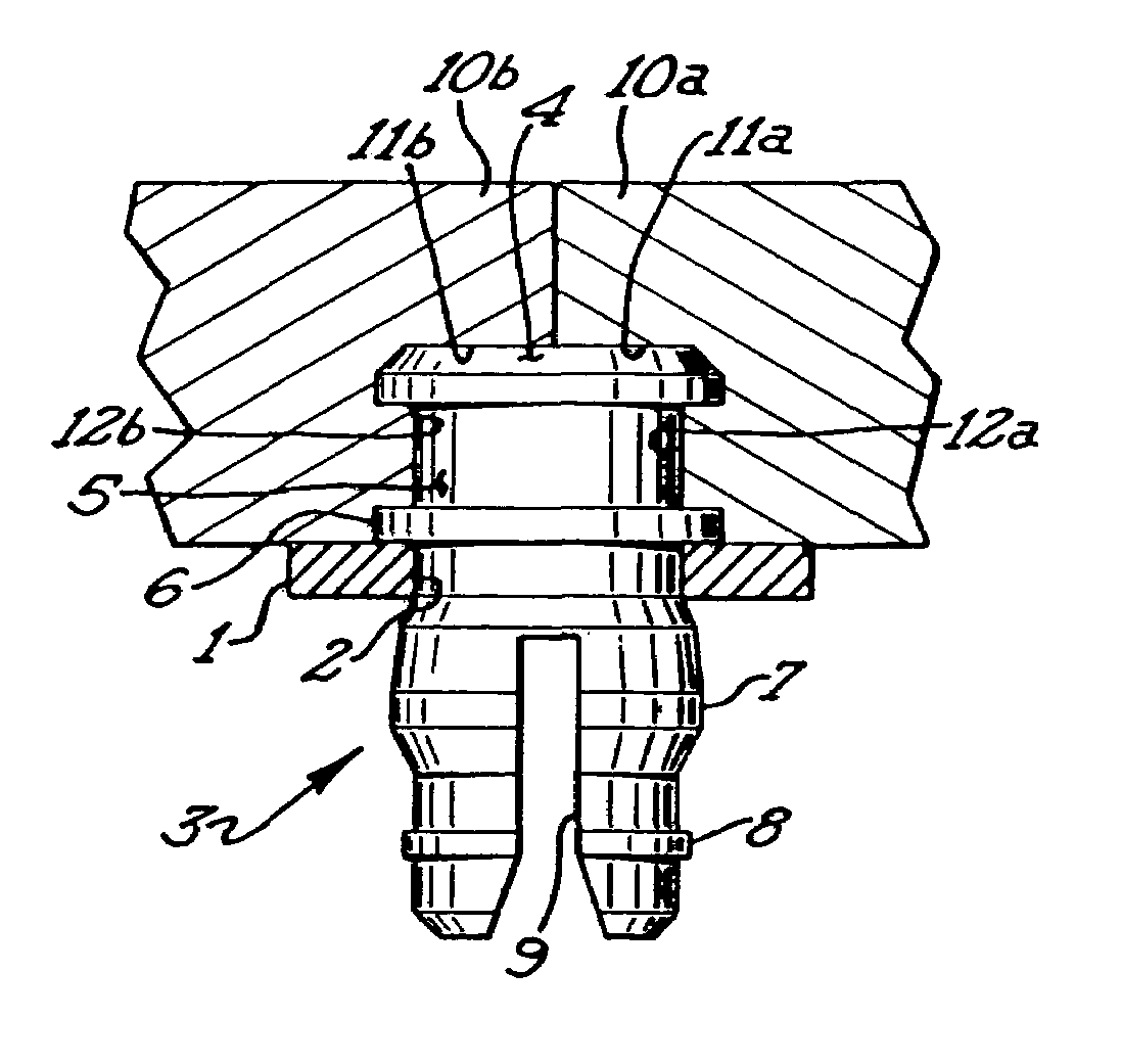
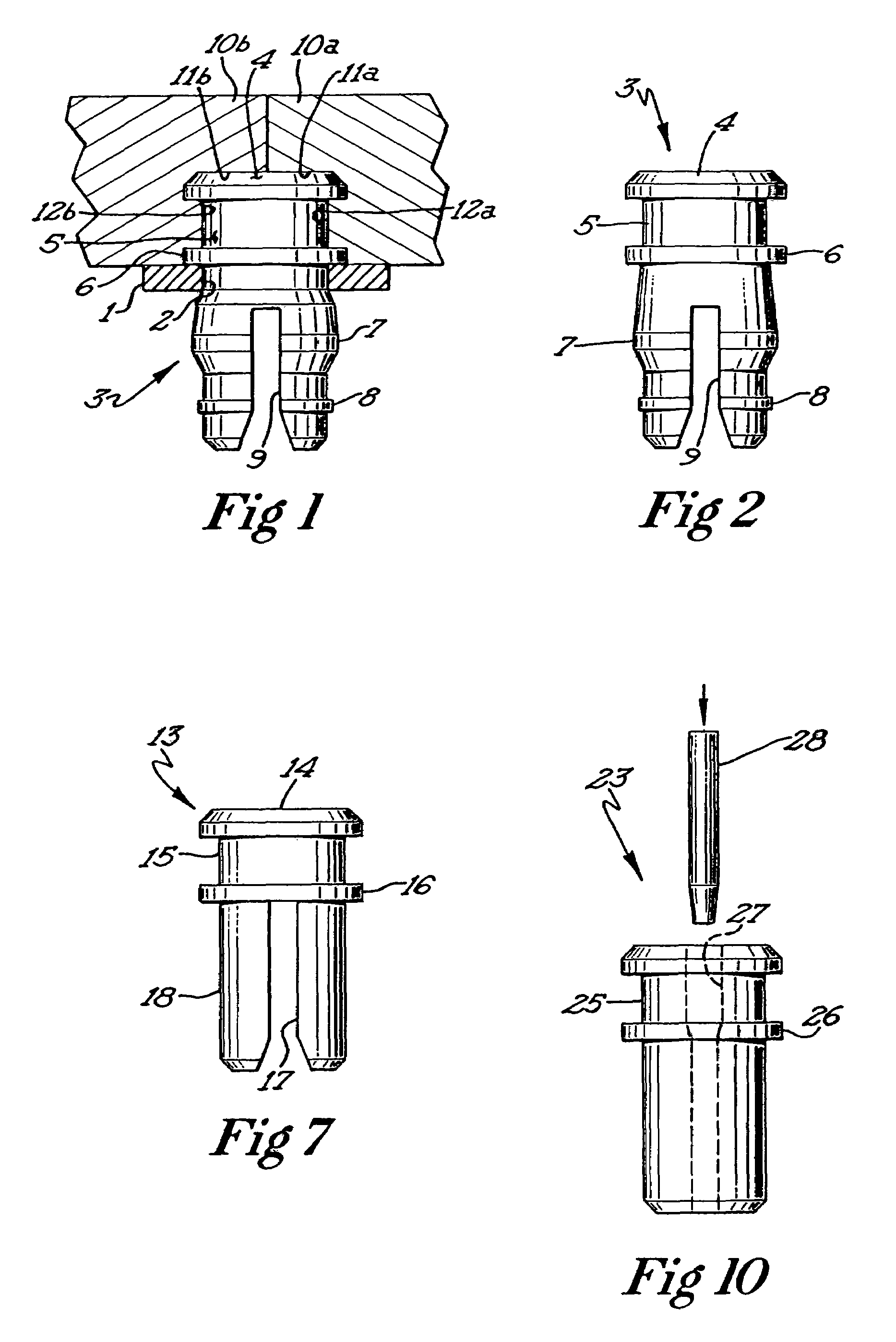
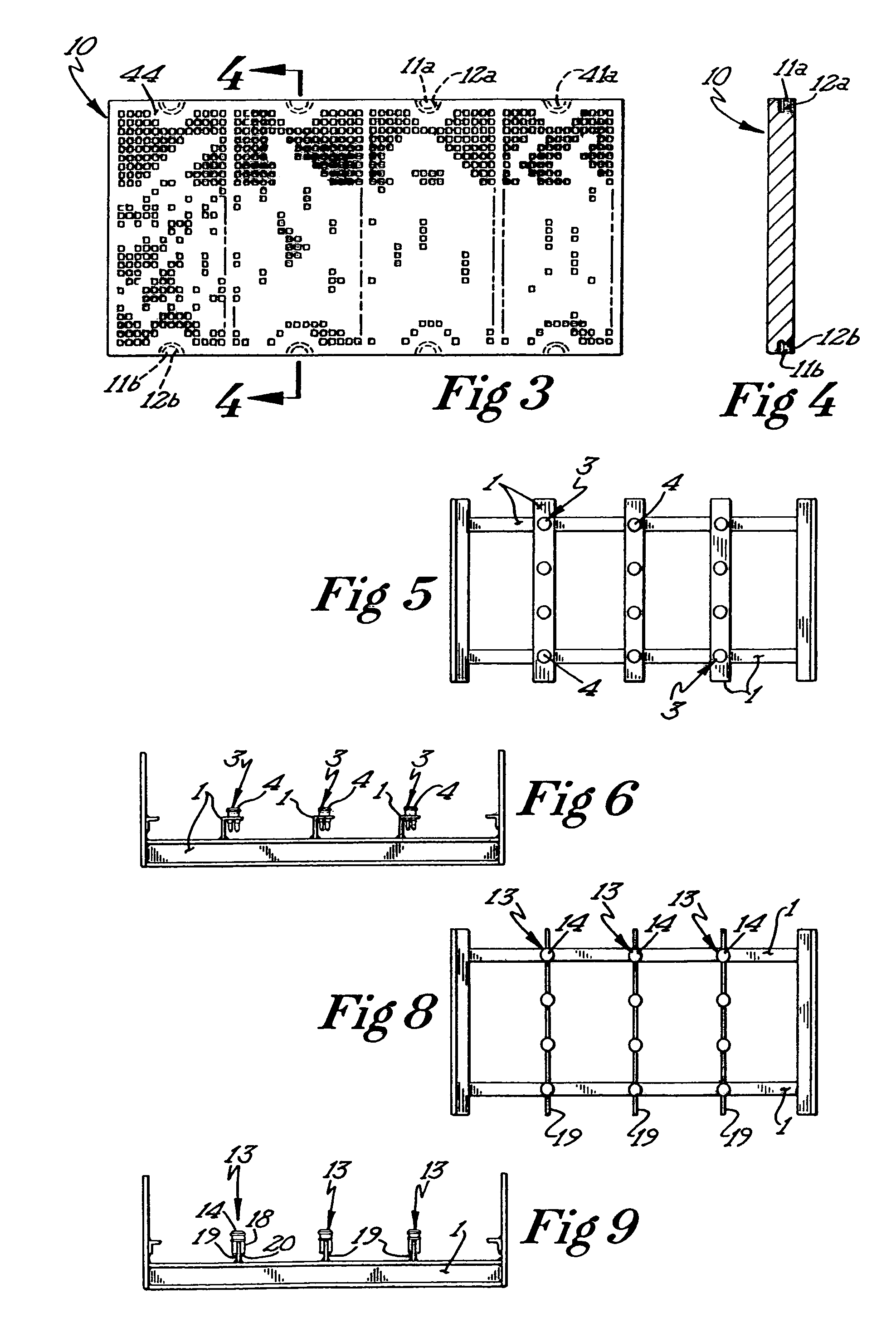
[0044]FIG. 1 shows only a part of the support frame, which is identified overall by reference number 1 The support frame 1 has a plurality of mounting holes 2, only one of which can be seen in FIG. 1. A mounting pin 3, fabricated out of an elastic plastic such as polyurethane is inserted into each of these mounting holes 2 and press-fit tightly in place. Mounting pin 3 is provided at the top with a head 4, the outside edge of which is rounded or beveled at the top

[0045]Underneath the head 4, the mounting pin 3 is provided with a circumferential groove 5. Underneath the groove 5 there is a ring-shape...


PUM


Abstract

The invention pertains to a sieve bed for a sifting machine, consisting of rectangular sieve elements (10), which are attached to a support frame (1) with their edges abutting each other, the support frame being provided with mushroom-shaped mounting pins (3), each of which is provided with a head which engages in an interlocking manner in corresponding recesses (11a and 11b) of the sieve elements (10).To facilitate the assembly and disassembly of the sieve elements in a sieve bed of this type and to protect the connection from premature wear the invention proposes that the receptacle (11) for the head (4) of the mounting pin (3) be closed off at the top; that the receptacle (11) for the head (4) of the mounting pin (3) be provided at the bottom with an entrance opening for the head (4) of the mounting pin (3); and that the wall of the receptacle (11) be provided with an inward-projecting bead (12), which can be snapped under the head (4) of the mounting pin (3).

Description

CROSS REFERENCES[0001]This application is a continuation of U.S. patent application Ser. No. 09 / 936,718 filed on Feb. 13, 2002, now U.S. Pat. No. 6,634,505 which is itself based upon PCT patent application no. WO 00 / 064599 A3 filed on Apr. 26, 2000 that was itself based upon German patent application no. 199 18 824.6 which was filed on Apr. 26, 1999.BACKGROUND OF THE INVENTION[0002]The invention pertains to an improved sieve bed for a sifting machine. More particularly, the invention relates to an improved mounting pin that allows for a maximum useful surface area for the sieve bed and which also securely mounts a plurality of sieve elements on a support frame of the sieve bed.BRIEF DESCRIPTION OF THE RELATED ART[0003]Various structures for screening or sifting particulate materials are known in the art. In general, a screening or sifting machine consists of a plurality of sieve elements (also referred to as screening panels and screen modules, among others) that are attached to a s...

Claims


Application Information

Patent Timeline
IPC IPC(8): B07B1/46F16B5/00F16B19/10
CPCB07B1/4645F16B5/0036F16B5/0056F16B19/1081B07B2201/02
Inventor SAWALL, KIRKDITLEFSEN, DAVID H.KUPER, ROLAND E.
Owner WEIR SLURRY GRP INC
Learn More