Projection display apparatus

a projection display and display device technology, applied in the field of projection display devices, can solve the problems of complicated optical configuration of reflection type projection display devices, and difficult to achieve full transmission, so as to reduce interference fringes and high grade

Active Publication Date: 2007-09-25
JVC KENWOOD CORP
View PDF7 Cites 4 Cited by
  • Summary
  • Abstract
  • Description
  • Claims
  • Application Information

AI Technical Summary

Benefits of technology

[0012]The present invention has been developed in view of the above points, and an object of the present invention is to provide a projection display apparatus which can reduce interference fringes of projected images and project an image of high grade.
[0014]According to the projection display apparatus of the present invention, the reflection type spatial light modulation elements are arranged in such a manner that distances between a screen and the respective reflection type spatial light modulation elements become different from each other, the reflection type spatial light modulation elements having a configuration in which two reflection type spatial light modulation elements are arranged with respect to one polarizing beam splitter, and an axial chromatic aberration of a projection image forming lens is provided in accordance with a difference between the distances. As a result, it is possible to provide the projection display apparatus which can reduce interference fringes of images projected onto the screen and project an image of high grade. In particular, the present invention demonstrates an advantage in an improvement of an image grade of a dark image.
[0017]According to the projection display apparatus of the present invention, the reflection type spatial light modulation elements are arranged in such a manner that distances between a screen and the respective reflection type spatial light modulation elements become different from each other, the reflection type spatial light modulation elements having a configuration in which the two reflection type spatial light modulation elements are arranged with respect to one polarizing beam splitter, and a light transparent member having an axial chromatic aberration provided thereto in accordance with a difference between the distances is arranged between the polarizing beam splitter and a projection image forming lens system. As a result, it is possible to provide a projection display apparatus which can reduce interference fringes of images projected onto the screen and project an image of high grade. In particular, the present invention demonstrates an advantage in an improvement of an image grade of a dark image.

Problems solved by technology

A scheme using reflection type spatial light modulation elements as a color projection display apparatus is advantageous in an increase in resolution but has a tendency that an optical configuration is complicated.
Usually, two or more polarizing beam splitters must be operated with respect to one spatial light modulation element in order to realize high contrast, and this makes the optical configuration of the reflection type projection display apparatus complicated.
Considering general characteristics of the polarization split surface of this polarizing beam splitter, it is difficult to achieve full transmission, i.e., 100% of transmission, and slight reflection occurs.
Therefore, there is a problem that the color light as the object of attention which has been reflected by the reflection type spatial light modulation element corresponding to the color light as the object of attention interferes with the color light as the object of attention which has been reflected by the reflection type spatial light modulation element corresponding to one color light different from the color light as the object of attention on the screen onto which the color lights are projected, resulting in interference fringes.

Method used


Image

  • Projection display apparatus
  • Projection display apparatus
  • Projection display apparatus

Examples


embodiment 1

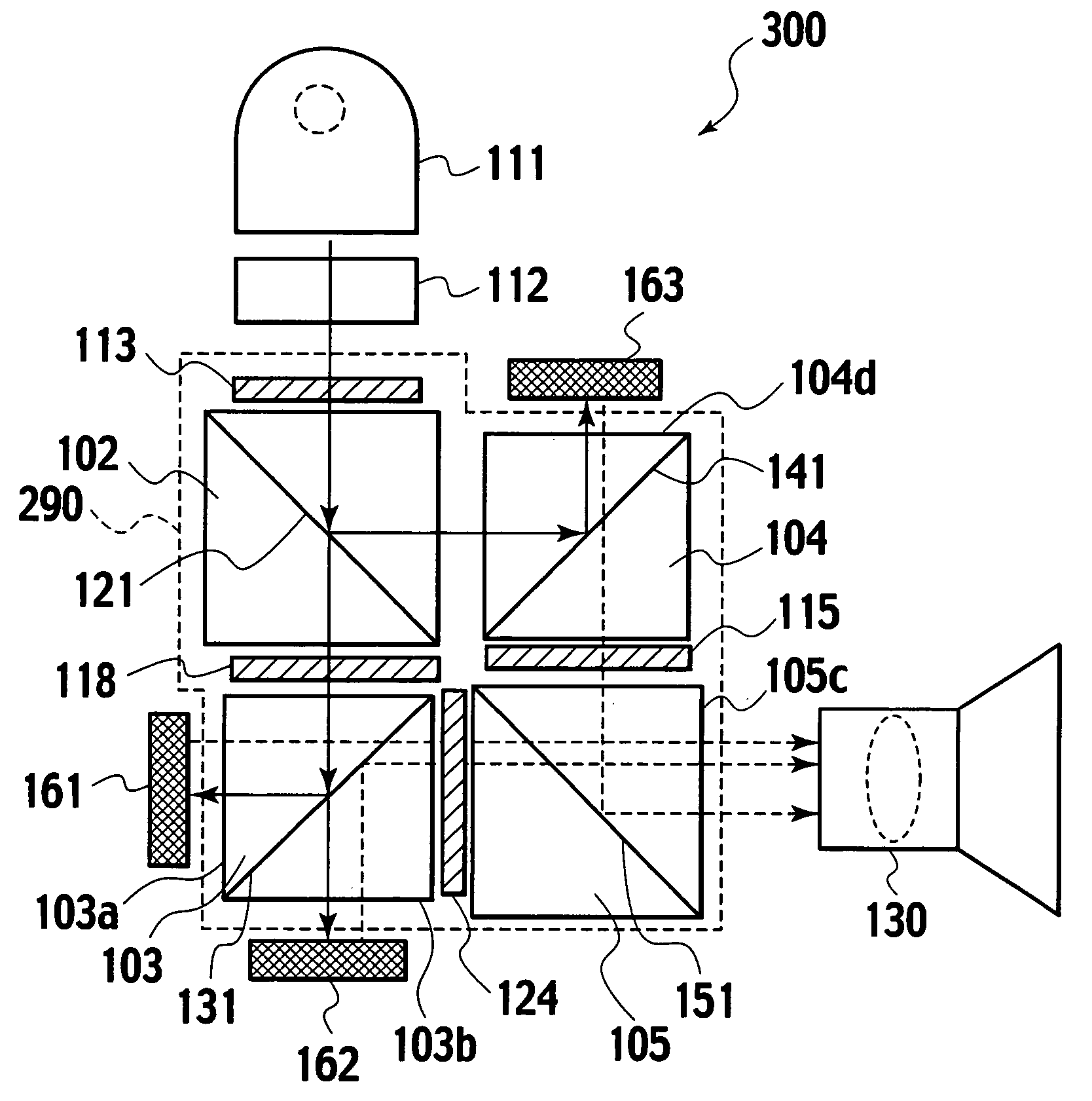
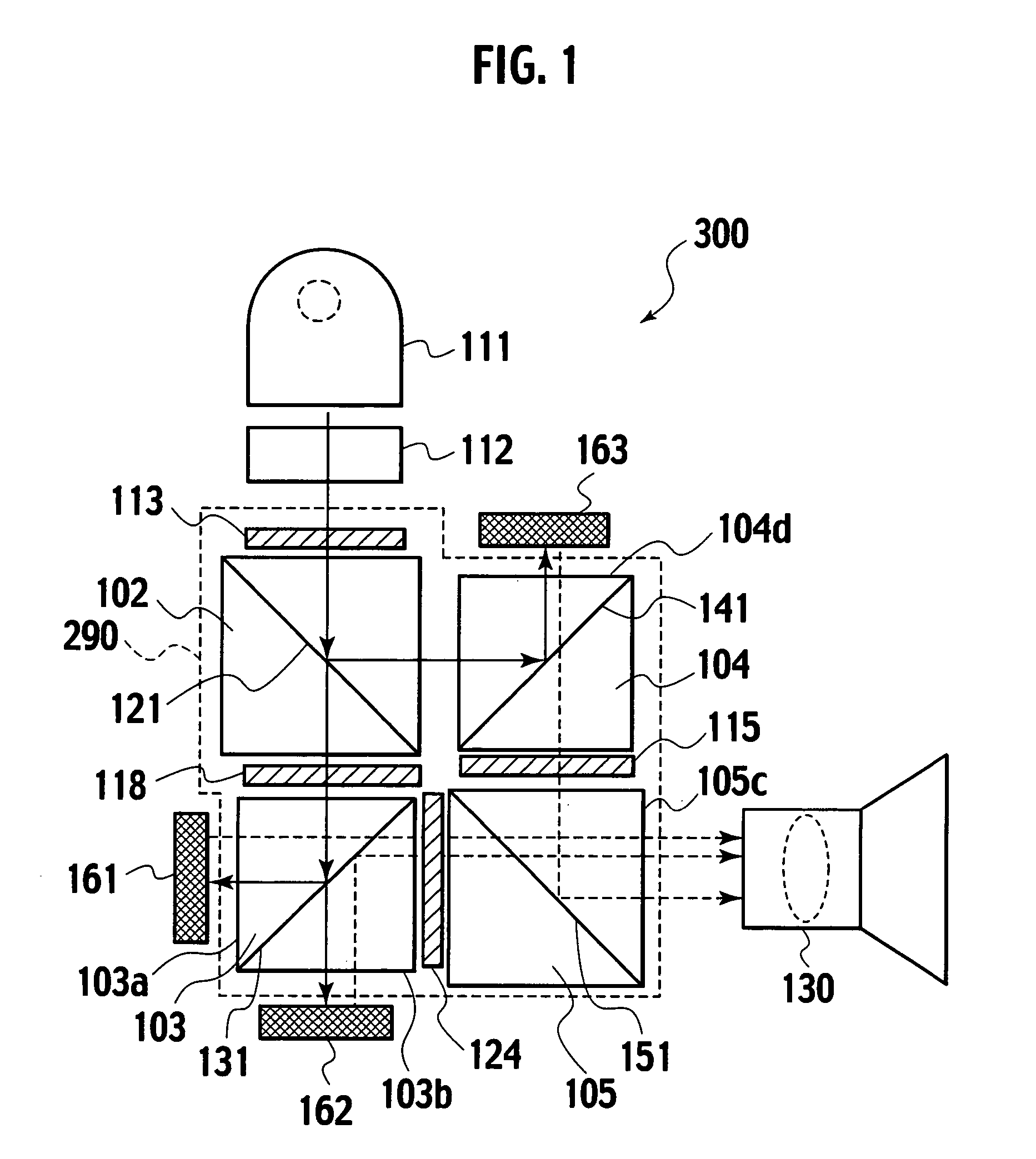
[0026]FIG. 1 is a schematic plan view showing an optical configuration of a projection display apparatus applied to Embodiment 1.

[0027]In a color separation / combination optical system 290 surrounded by a broken line, first, second and third polarizing beam splitters 102, 103 and 104 which serve as cubic or prismatic polarization split elements and a fourth polarizing beam splitter 105 which serves as a polarization combining element are arranged so that polarization split surfaces 121, 131, 141 and 151 of these polarizing beam splitters form a substantially X-like shape as a whole. Moreover, a color polarizer 113 having a function of rotating polarized wave surfaces of an R light and a G light by 90 degrees is provided on a light transmission surface of the first polarizing beam splitter 102 on an incidence side (an upper surface of the first polarizing beam splitter), and a color polarizer 118 having a function of rotating a polarized wave surface of the G light by 90° is provided ...

embodiment 2

[0060]An optical configuration of a projection display apparatus applied to Embodiment 2 will now be described with reference to FIG. 4. This drawing is a schematic plan view showing an optical configuration of a projection display apparatus applied to Embodiment 2, and like reference numerals denote the same configurations as those in Embodiment 1 mentioned above.

[0061]FIG. 4 is a schematic plan view showing the optical configuration of the projection display apparatus applied to Embodiment 2.

[0062]A color separation / combination optical system 290 surrounded by a broken line has a structure in which first, second and third polarizing beam splitters 102, 103 and 104 serving as cubic or prismatic polarization split elements and a fourth polarizing beam splitter 105 serving as a polarization combining element are arranged in such a manner that their polarization split surfaces 121, 131, 141 and 151 form a substantially X-like shape as a whole. Furthermore, a color polarizer 113 having...


PUM

PropertyMeasurementUnit
back focal distanceaaaaaaaaaa
thicknessaaaaaaaaaa

Abstract

A white light emitted from a light source is homogenized by an integrator optical system, transmitted through a color polarizer (113) to be turned into an R light and a G light of a P polarized light, and transmitted through a color polarizer (118) to be turned into a G light of an S polarized light and an R light of a P polarized light. These R light and G light are subjected to light modulation in a reflection type spatial light modulation element for G and a reflection type spatial light modulation element for R arranged at unequal distances from a polarization split surface of a polarizing beam splitter (103), and emitted from a projection lens having an axial chromatic aberration corresponding to the unequal distances.

Description

BACKGROUND OF THE INVENTION[0001]1. Field of the Invention[0002]The present invention relates to a projection display apparatus using reflection type spatial light modulation elements.[0003]2. Description of the Related Art[0004]A color projection display apparatus separates color lights of R (red), G (green) and B (blue) concerning three primary color lights from a white light, leads the separated color lights to spatial light modulation elements for corresponding colors, combines the color lights subjected to light modulation by the spatial light modulation elements in accordance with a video signal, and projects a combined light, thereby displaying a color projected image on a screen.[0005]A scheme using reflection type spatial light modulation elements as a color projection display apparatus is advantageous in an increase in resolution but has a tendency that an optical configuration is complicated. That is because the projection display apparatus to which the reflection type sp...

Claims


Application Information

Patent Timeline
Patent Type & Authority Patents(United States)
IPC IPC(8): G03B21/14G02F1/1335H04N3/26G03B21/20H04N9/31
CPCH04N9/3105H04N9/317H04N9/3197G03B21/2073G02B27/1026G02B27/283G02B27/288
Inventor KOBAYASHI, MANABUTAKAHASHI, RYUSAKU
Owner JVC KENWOOD CORP
Why Eureka
Try Eureka