
Index matching layers

a technology of index matching and layers, applied in the field of systems, can solve the problems of generating interference effects, reducing the appearance of the lens, and combining reflections from the different interfaces destructively or constructively, and achieving the effect of reducing interference fringes

Active Publication Date: 2019-10-15
HOYA OPTICAL LABS OF AMERICA INC
View PDF6 Cites 1 Cited by
  • Summary
  • Abstract
  • Description
  • Claims
  • Application Information

AI Technical Summary

Benefits of technology

[0019]These objectives are further achieved by the present invention, in part, by providing a method for reducing interference fringes observed in an optical article comprising: obtaining a base lens substrate having a first refractive index; forming an index matching system on a surface of the base lens substrate having a plurality of material layers with different refractive indices relative to one another; and applying a coating on a surface of the index matching system having a second refractive index that differs from the first refractive index by 0.08 or greater.

Problems solved by technology

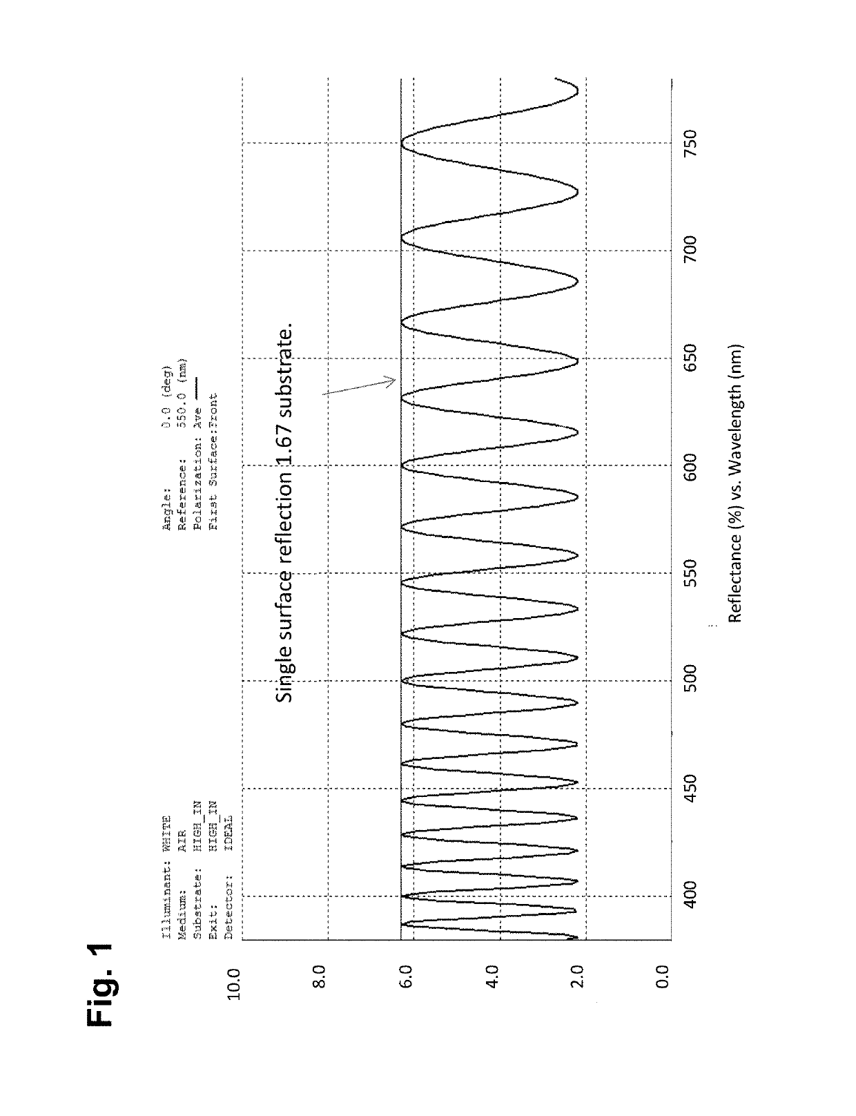
However, the common use of low refractive index backside hard-coatings creates interference fringes on such lenses which can strongly detract from the appearance of the lens.
This is especially the case when the hard-coating is not closely index matched to the lens material.
Since light is a wave the reflections from the different interfaces combine destructively or constructively depending on the wavelength of light.
Since typical hard-coatings are deposited by dip processes, they are not perfectly uniform which means the reflection spectra changes over the lens surface.
This, in turn, generates interference effects similar to the fringes observed on a soap bubble and significantly detracts from the appearance and performance of a lens
However, there are several limitations that can prevent this from occurring.
First, hard-coatings are not available in all commercially used lens material indices.
However, new lens material development is often in advance or ahead of the development of hard-coatings having similar indices.
Therefore, it is often the case that lens materials new to the market place do not have closely refractive index matched hard-coatings available.
The second limitation relates to processing a lens blank into a finished lens.
Unfortunately, this desirable decrease in lens thickness is often accompanied by the degradation in the appearance of the lens due to the index mismatch between the hard-coating and the lens.
Applying an antireflective, AR, coating to such a lens can make the above-described problem worse.
This can result in distortion of the color of the antireflection coating.
Since the hard-coating thickness changes over the lens surface, the distortion changes over the lens surface making it very noticeable.
A third limitation relates to the use of index matching hard-coatings for photochromic lenses.
This creates a potential problem when the photochromic functionality is combined with high index hard-coatings.
The reduced transmission of HC-B from 300 to 380 nm will degrade the performance of a UV activated photochromic material.
However, this would then lead to the same color variation and degraded appearance as described above.

Method used


Image

  • Index matching layers
  • Index matching layers
  • Index matching layers

Examples


example 1

[0064]With reference to FIGS. 4 and 8-10, a Design 1a of the inventive index matching system was modeled. With reference to FIGS. 8 and 9, the Design 1a employed the index matching system 12 formed of a first layer 22 having a thickness of 4.2 nanometers of ZrO2 applied directly on the surface 18 of the lens substrate 14 (FIG. 3); a second layer 24 having a thickness of 40.0 nanometers of SiO2 applied directly on a surface 26 of the first layer 22; and a third layer 28 having a thickness of 6.3 nanometers of ZrO2 applied directly on a surface 30 of the second layer 24. A surface 32 of the index matching system 12 is a surface upon which the hard-coating 16 is applied or otherwise formed.

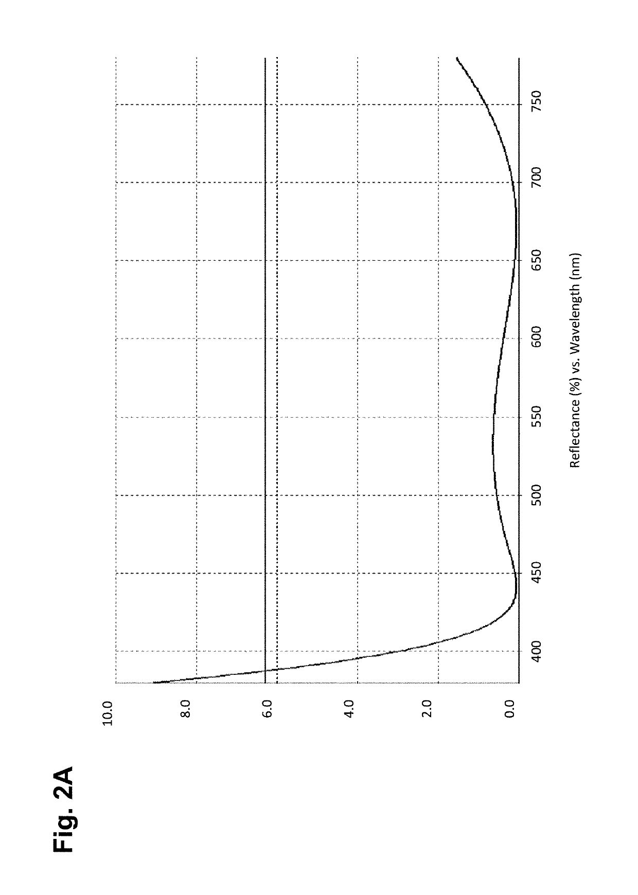
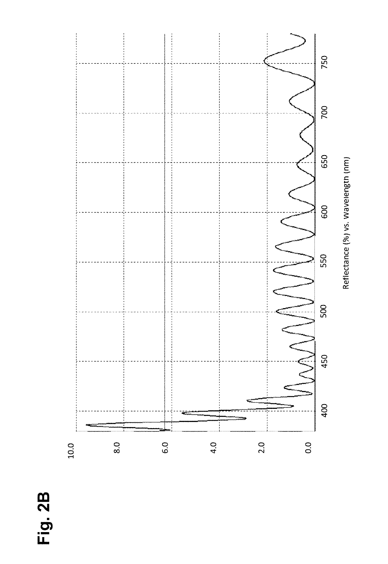
[0065]FIG. 10 compares the modeled reflection spectra for (1) a lens employing the above described inventive index matching system 12, Design 1a, disposed between a 1.67 index lens substrate 14 and a 1.5 index, mismatched hard-coating 16; (2) a lens employing a 1.67 index lens substrate 14 with an in...

example 2

[0066]With reference to FIGS. 4, 8, 11, and 12, a Design 1b of the inventive index matching system was modeled. With reference to FIG. 11, the Design 1b employed the index matching system 12 formed of a first layer 22 having a thickness of 7.0 nanometers of ZrO2 applied directly on the surface 18 of the lens substrate 14 (FIG. 3); a second layer 24 having a thickness of 50.0 nanometers of SiO2 applied directly on a surface 26 of the first layer 22; and a third layer 28 having a thickness of 6.3 nanometers of ZrO2 applied directly on a surface 30 of the second layer 24. A surface 32 of the index matching system 12 is a surface upon which the hard-coating 16 is applied or otherwise formed.

[0067]FIG. 12 compares the modeled reflection spectra for (1) a lens employing the above described index matching system of Design 1a, disposed between a 1.67 index lens substrate 14 and a 1.5 index, mismatched hard-coating 16; (2) a lens employing the above described index matching system of Design ...

example 3

[0069]FIGS. 13A and 13B show photographs comparing two 1.70 index lenses one employing the inventive index matching system (FIG. 13B) and the other lens not employing the inventive index matching system (FIG. 13A). Both lenses shown have a commercially available UV curable 1.5 index (approximate) backside hard-coating (for example UV-NV; Ultra Optics) applied as an outer most layer.

[0070]The benefit of the index matching system of the present invention is immediately obvious from comparison of FIGS. 13A and 13B. In the standard mismatched index lens and hard-coating configuration (FIG. 13A) there are many colored fringes of irregular shapes that are tightly packed. This effect detracts from the appearance of the lens. With the inventive index matching system described above employed between the hard-coating and the lens surface (FIG. 13B), the number of fringes is greatly reduced and are spaced much further apart, hence, significantly improving the appearance of the lens.


PUM


Abstract

Optical devices such as eyeglass lenses and digital displays having improved optical characteristics achieved, in part, through incorporation of an index matching system between material layers having different refractive indices.

Description

RELATED APPLICATIONS[0001]This application claims benefit of and priority to U.S. Provisional Application Ser. No. 62 / 382,924 filed Sep. 2, 2016, entitled Index Matching Layers, which is hereby incorporated herein by reference in its entirety.FIELD OF THE INVENTION[0002]The present invention relates to systems and methods for reducing interference fringes in optical and display applications and, more particularly, to the incorporation of refractive index matching systems between refractive mismatched layers and / or substrates.BACKGROUND OF THE INVENTION[0003]High refractive index ophthalmic eyeglass lenses are attractive options for their increased refractive power and decreased thickness. However, the common use of low refractive index backside hard-coatings creates interference fringes on such lenses which can strongly detract from the appearance of the lens.[0004]Common ophthalmic lenses are made from relatively soft polymeric materials prone to scratching. Hence, in order to prov...

Claims


Application Information

Patent Timeline
Patent Type & Authority Patents(United States)
IPC IPC(8): G02C7/02G02B1/111G02B5/23
CPCG02C7/02G02B1/111G02B5/23G02B1/115G02C7/022
Inventor BROWN, JEFFBOULINEAU, MICHAEL S.MARSHALL, MICHAELREYNOLDS, TIM
Owner HOYA OPTICAL LABS OF AMERICA INC
Learn More