
High efficiency axial fan

a high-efficiency, axial fan technology, applied in the direction of propellers, propulsive elements, water-acting propulsive elements, etc., can solve the problems of limited high-pressure values, limited axial dimensions of fans constructed in accordance with the above-mentioned patent, and large diameters, etc., to achieve high pressure, low noise value, and good air flow rate

Inactive Publication Date: 2007-09-25
SPAL AUTOMOTIVE
View PDF7 Cites 10 Cited by
  • Summary
  • Abstract
  • Description
  • Claims
  • Application Information

AI Technical Summary

Benefits of technology

"The present invention aims to provide a fan that has limited dimensions and can create good air flow with high pressure and low noise levels. The fan has a central hub and a plurality of blades that are designed to have an aerodynamic profile that maximizes air flow and pressure. The blades are made from sections with profiles that extend in the direction of their center line. The fan has a concave leading edge and a convex trailing edge, which are both defined by circular arc segments. The design of the fan allows for efficient air flow and pressure while maintaining limited dimensions."

Problems solved by technology

Fans constructed in accordance with said patent provide good efficiency and low noise, but have limits as regards the possibility of achieving high pressure values, since the blades are made with profiles whose centre line is relatively short compared with the blade radial extension.
Moreover, fans constructed in accordance with the above-mentioned patent have a limited axial dimension, but a relatively large diameter.
For the exchanger units of heating and / or air conditioning systems for the interior of motor vehicles the overall dimensions of the fan must be limited, which means that the diameter must also be limited, whilst good air flow rates are required with high pressure and low noise.

Method used


Image

  • High efficiency axial fan
  • High efficiency axial fan
  • High efficiency axial fan

Examples


Embodiment Construction

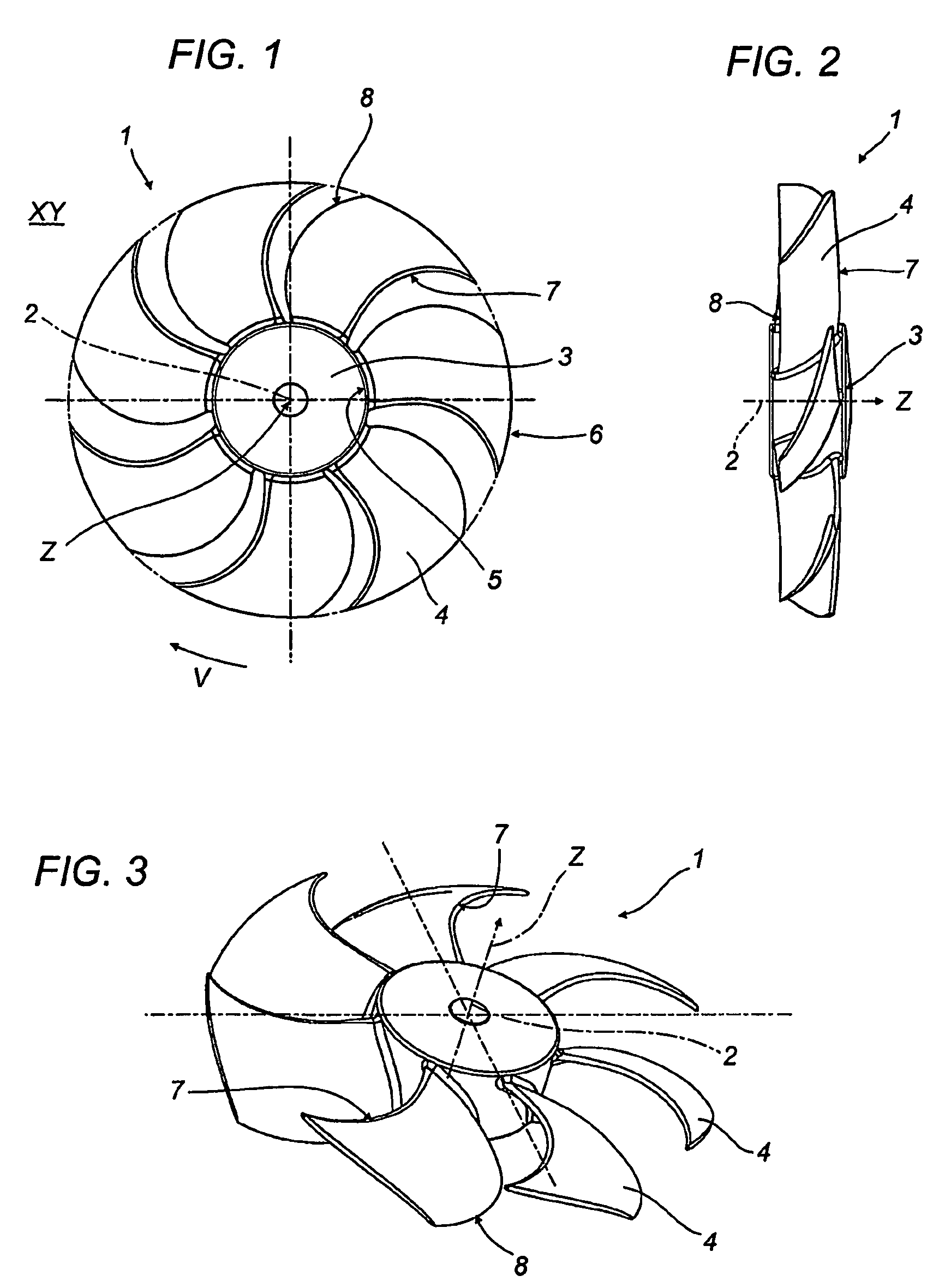
[0021]With reference to the accompanying drawings, the fan 1 rotates about an axis 2 in a plane XY and comprises a central hub 3, with a centre o, to which a plurality of blades 4 are connected, the blades being curved in the fan 1 plane of rotation XY.

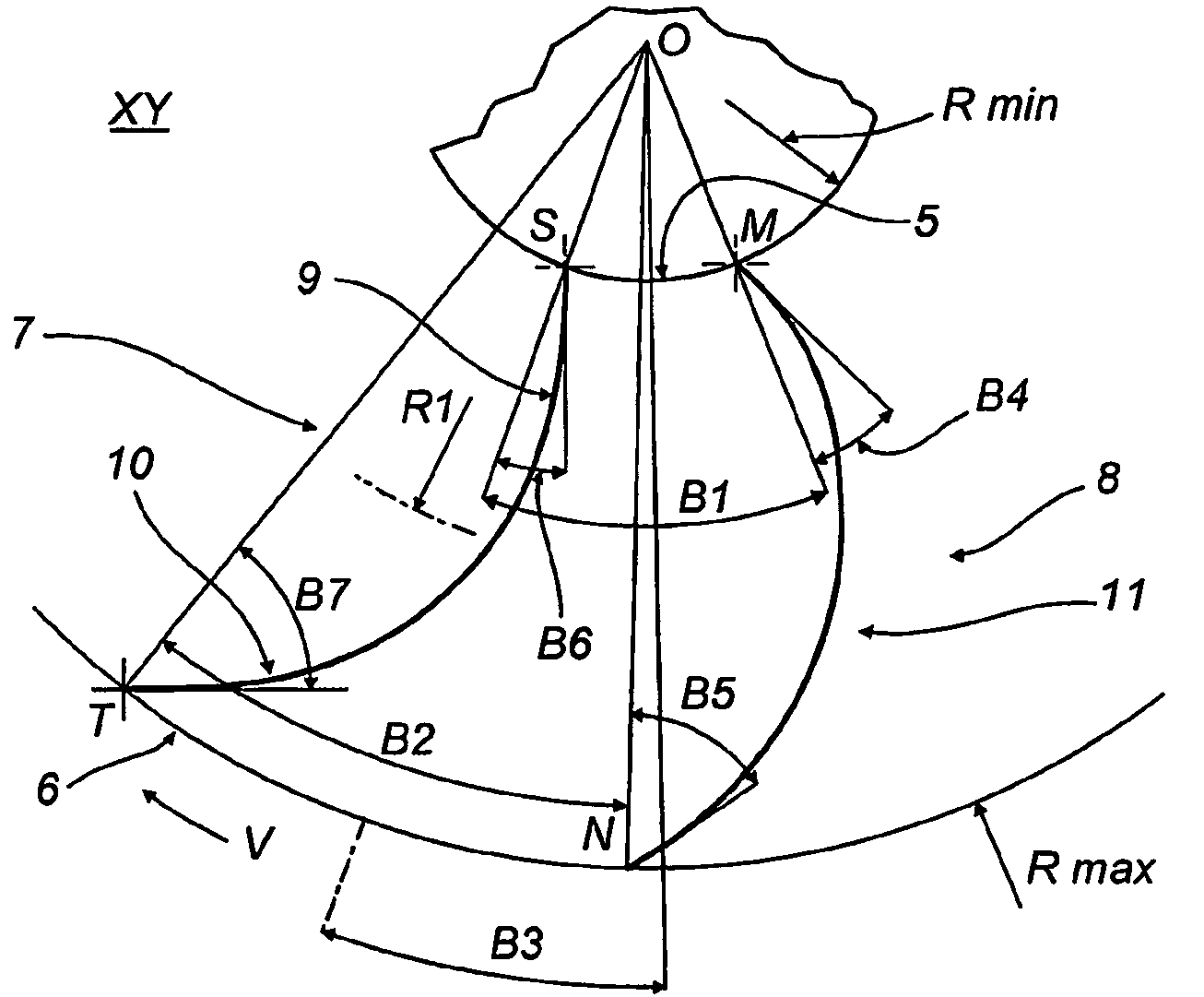
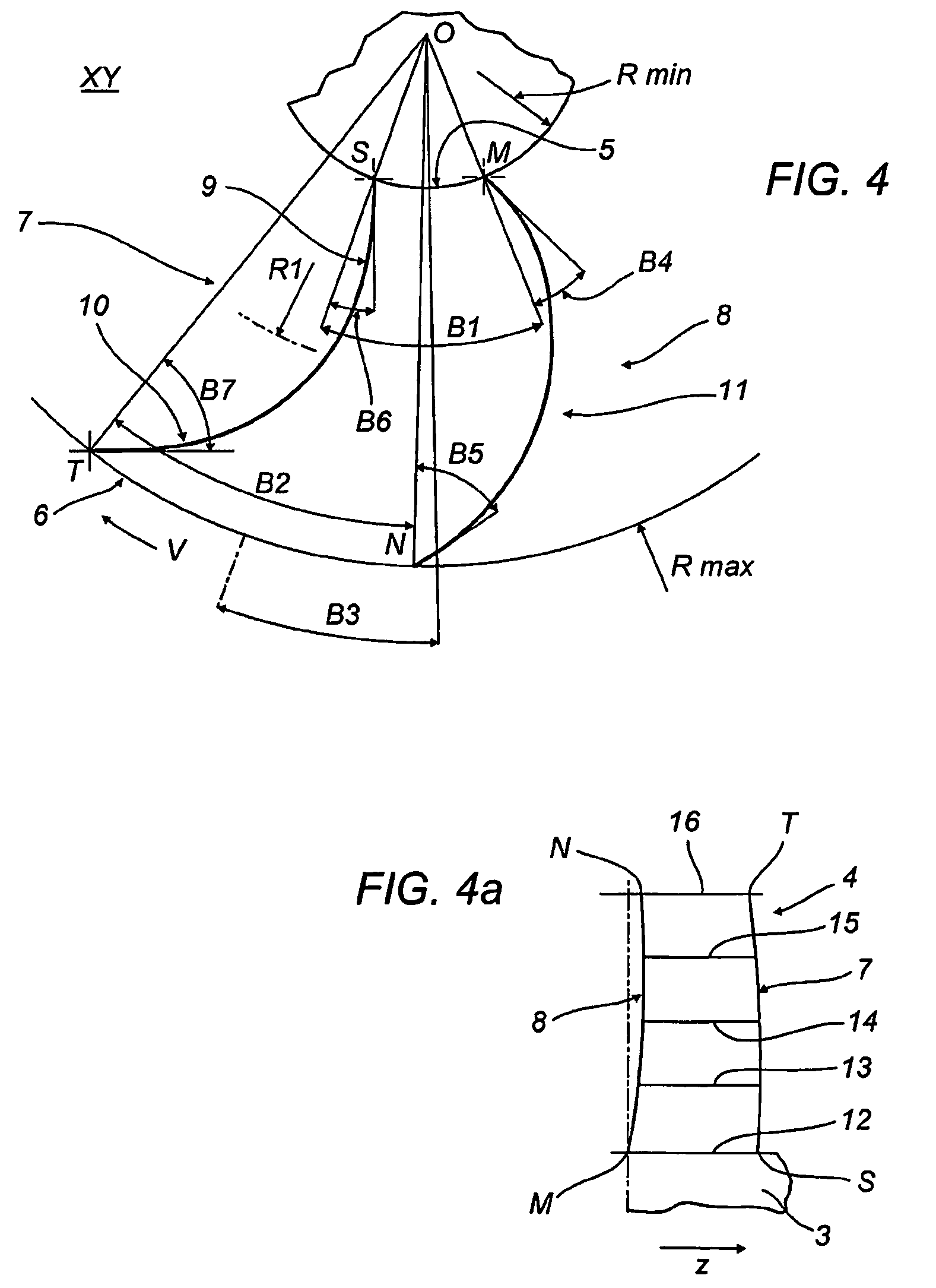
[0022]The blades 4 have a root 5, a tip 6 and are delimited by a concave leading edge 7 and a convex trailing edge 8.

[0023]For the best results in terms of efficiency, flow rate and air pressure, the fan 1 rotates with a direction of rotation V, illustrated in FIGS. 1 and 4, so that the tip 6 of each blade 4 encounters the air flow before the root 5.

[0024]FIG. 4 illustrates an example of the geometric characteristics of a blade 4 the leading edge 7 is delimited by two circular arc segments 9, 10, and the trailing edge 8 is delimited by one circular arc segment 11.

[0025]In the leading edge 7, a radius labelled R1 is the point of change from one circular arc segment to the other circular arc segment.

[0026]According to the example in FIG...


PUM


Abstract

Disclosed is an axial fan (1) rotating in a plane (XY) about an axis (2) having a central hub (3) and a plurality of blades (4), which have a root (5) and a tip (6). The blades (4) are delimited by a concave leading edge (7), whose projection in the fan plane of rotation (XY) is defined by two circular arc segments, and a convex trailing edge (8), whose projection in the fan plane of rotation (XY) is defined by one circular arc segment. The blades (4) are made from sections with aerodynamic profiles relatively extending in the direction of their centre line, providing good flow rate and air pressure relative to the overall dimensions of the fan.

Description

TECHNICAL FIELD[0001]The present invention relates to an axial fan with blades angled in the fan plane of rotation.[0002]The fan according to the present invention may be used in various applications, for example, to move air through a heat exchanger, or radiator, of a cooling system for the engine of a motor vehicle or the like.[0003]A specific sector for application of the fan according to the present invention is that of conditioning systems, that is to say, heating and / or air conditioning for the interior of motor vehicles.BACKGROUND ART[0004]Fans of this type must satisfy various requirements, including: low noise level, high efficiency, compactness, capacity to achieve good pressure and flow rate values.[0005]Patent EP-O 553 598, by the same Applicant, presents a fan with blades delimited at the leading edge and trailing edge by two curves which are two circular arcs when projected in the fan plane of rotation.[0006]Fans constructed in accordance with said patent provide good ...

Claims


Application Information

Patent Timeline
Patent Type & Authority Patents(United States)
IPC IPC(8): F04D29/38
CPCF04D29/325F04D29/384Y10S416/05F04D29/386
Inventor SPAGGIARI, ALESSANDRO
Owner SPAL AUTOMOTIVE
Learn More