Mass flow meter composed of two measuring tubes with a connecting device between them

a technology of mass flow meter and connecting device, which is applied in the direction of mass flow measurement device, measurement device, instrument, etc., can solve the problems of interference with the measuring signal, two or more measuring tubes employed in practical application, and still need improvemen

Active Publication Date: 2007-10-02
KRONE GMBH
View PDF12 Cites 14 Cited by
  • Summary
  • Abstract
  • Description
  • Claims
  • Application Information

AI Technical Summary

Benefits of technology

[0005]It is, therefore, the objective of this invention to introduce a Coriolis mass flowmeter in which the effect of the perpendicular oscillations of the measuring tubes on the excitation oscillations of the measuring tubes is minimized.
[0007]In other words, the invention provides for the flexural strength of the connecting device in terms of flections along the common plane of the measuring tubes in which the excitation oscillations generally occur to be greater than the torsional rigidity of the connecting device in terms of torsional oscillations around an axis that links the points of contact of the connecting devices with the two measuring tubes. Due to the fact that these torsional oscillations of the connecting device are stimulated when, in phase opposition, oscillations of the measuring tubes are generated perpendicular to their common plane, whereas flexural oscillations of the connecting device occur in the common plane of the measuring tubes when in that plane, the measuring tubes are stimulated into excitation oscillations, these two types of oscillations—excitation oscillations on the one hand and perpendicular oscillations on the other—are affected in different ways. This is because, while the connecting device offers lower flexural resistance to antiphase oscillations perpendicular to the common plane of the measuring tube, there is greater flexural resistance for oscillations of the measuring tubes along their common plane in which the oscillatory stimulation takes place. The overall result is a good frequency separation between the excitation oscillations and the perpendicular oscillations of the measuring tubes, which ultimately reduces any impact on the measuring signal by the mutual effect between the excitation oscillations and oscillations perpendicular to the latter.
[0011]It is possible to design the connecting device in such fashion that the reinforcing plates and the connecting plate are of the same thickness. This allows for simple production of the connecting device, for instance from a single plate, by suitably bending its peripheral areas. According to a preferred embodiment of the invention, however, the connecting plate is thicker than the reinforcing plates. The result is an even greater frequency separation between the excitation oscillations and the perpendicular oscillations of the measuring tubes. Comparatively thinner reinforcing plates substantially reduce the torsional rigidity for torsional oscillations around the connecting line between the two measuring tubes in relation to the flexural strength for flections in the common plane of the measuring tubes. It follows that a connecting device with thinner reinforcing plates offers significantly greater flexural resistance to the excitation oscillations in the common plane of the measuring tubes than to perpendicular oscillations that engender torsional oscillations of the connecting device.

Problems solved by technology

In that respect, however, Coriolis mass flowmeters with two or more measuring tubes employed in practical application are still in need of improvement since the effect on the excitation oscillations by perpendicular oscillations of the measuring tubes, and thus the interference with the measuring signal, is still too extensive.

Method used


Image

  • Mass flow meter composed of two measuring tubes with a connecting device between them
  • Mass flow meter composed of two measuring tubes with a connecting device between them
  • Mass flow meter composed of two measuring tubes with a connecting device between them

Examples


Embodiment Construction

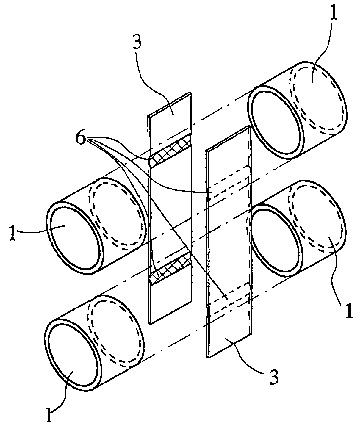
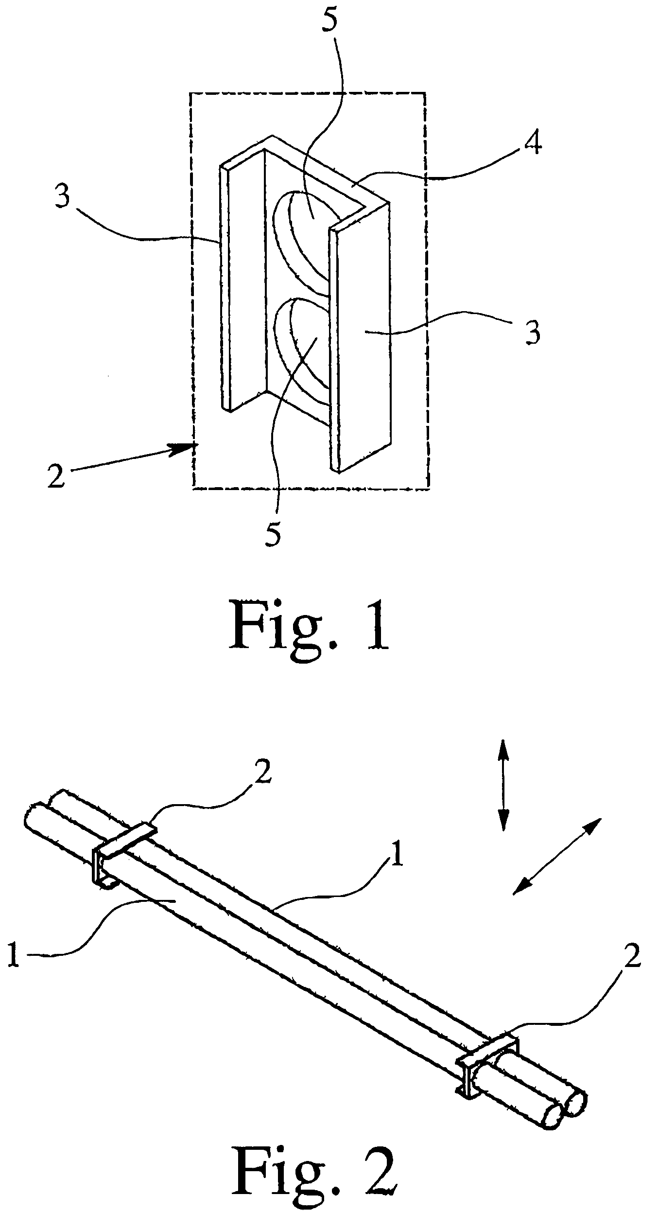
[0023]FIGS. 1 and 2 show the essential, novel details of a Coriolis mass flowmeter according to a first preferred embodiment of the invention. They illustrate two mutually parallel measuring tubes 1 provided with two connecting devices 2. The connecting devices 2 have an essentially U-shaped cross-sectional profile composed of two reinforcing plates 3 that are connected with each other via a connecting plate 4 in a manner whereby these reinforcing plates 3 are aligned parallel to each other and at a right angle to the connecting plate 4. The reinforcing plates 3 are thinner than the connecting plate 4, thus creating the above-mentioned effect whereby the connecting devices 2 offer substantially less flexural resistance to torsional oscillations than to flexural oscillations along the common plane of the measuring tubes 1.

[0024]The connecting plate 4 is provided with two boreholes 5 whose inner diameter essentially matches the outer diameter of the measuring tubes 1. It is thus possi...


PUM


Abstract

A mass flowmeter employing the Coriolis principle incorporates in at least one section two measuring tubes that extend along a common plane, as well as a connecting device that connects the two measuring tubes in the section in which they extend along the common plane. The connecting device is designed and positioned in a manner whereby its flexural strength for flections in the common plane of the measuring tubes is greater than its torsional rigidity for torsional oscillations around the connecting line between the two measuring tubes. This achieves good frequency separation between the excitation oscillations generated in the common plane of the measuring tubes and the oscillations of the measuring tubes perpendicular to the former.

Description

BACKGROUND OF THE INVENTION[0001]This invention relates to a mass flowmeter that employs the Coriolis principle and incorporates in at least one section two measuring tubes extending in a common plane, as well as a connecting device by means of which the two measuring tubes are interconnected within the section in which they extend along the said common plane.[0002]Accordingly, the invention relates to Coriolis mass flowmeters that feature at least two measuring tubes which, when not oscillating, extend at least within one section along a common plane, typically parallel to each other. A key aspect in Coriolis mass flowmeters having two or more measuring tubes is the provision of at least one and, where appropriate, two connecting devices as referred to above. These connecting devices determine the effective length of the measuring range since they hold the measuring tubes in position, each defining an oscillation node. Therefore, connecting devices of this type are also known as os...

Claims


Application Information

Patent Timeline
Patent Type & Authority Patents(United States)
IPC IPC(8): G01F1/84
CPCG01F1/8495G01F1/8413
Inventor HUSSAIN, YOUSIFROLPH, CHRIS N.COOK, VINCENT
Owner KRONE GMBH
Why Eureka
Try Eureka