Heat transfer tube panel module and method of constructing exhaust heat recovery boiler using the module

a heat transfer tube and module technology, applied in the field of exhaust heat recovery boilers, can solve the problems of poor adaptability of the installation outside japan of the modules manufactured in japan, increase in the size of the module transporting and increase in the cost of transporting the module of the heat exchanger tube bundle panel

Active Publication Date: 2007-10-02
MITSUBISHI HITACHIPOWER SYST LTD
View PDF9 Cites 17 Cited by
  • Summary
  • Abstract
  • Description
  • Claims
  • Application Information

AI Technical Summary

Benefits of technology

[0010]However, in the construction method of the U.S. Pat. No. 859,550, the frame body housing the modules of the heat exchanger tube bundle panels becomes large in size since it can be used as it is as a main frame of the heat recovery boiler at the construction site. Therefore, the costs for transporting the modules of the heat exchanger tube bundle panels increase.
[0011]An objective of the invention is to provide a construction method for a heat recovery boiler which can reduce the transportation costs, prevent damage to the heat exchanger tube bundle panels during transportation, reduce the installation costs, and minimize waste material after installation, and a heat exchanger tube bundle panel module to be used for this method.
[0012]An additional objective of the invention is to provide a construction method for a heat recovery boiler that is most economical since the components forming the heat recovery boiler are formed into several modules and manufactured in the factory and transported to the site and assembled, and a heat exchanger tube bundle panel module to be used for this method.

Problems solved by technology

Therefore, the costs for transporting the modules of the heat exchanger tube bundle panels increase.
However, the modules with the structural members incorporated have a longer cross sectional area at the exhaust gas duct, and become large in size.
In the case of the large modules, the heat recovery boiler construction site is limited to a site such as a coastal area near a pier wherein a large barge can approach alongside due to transportation conditions, whereby installation outside Japan of the modules manufactured in Japan is poor in adaptability.

Method used


Image

  • Heat transfer tube panel module and method of constructing exhaust heat recovery boiler using the module
  • Heat transfer tube panel module and method of constructing exhaust heat recovery boiler using the module
  • Heat transfer tube panel module and method of constructing exhaust heat recovery boiler using the module

Examples


first embodiment

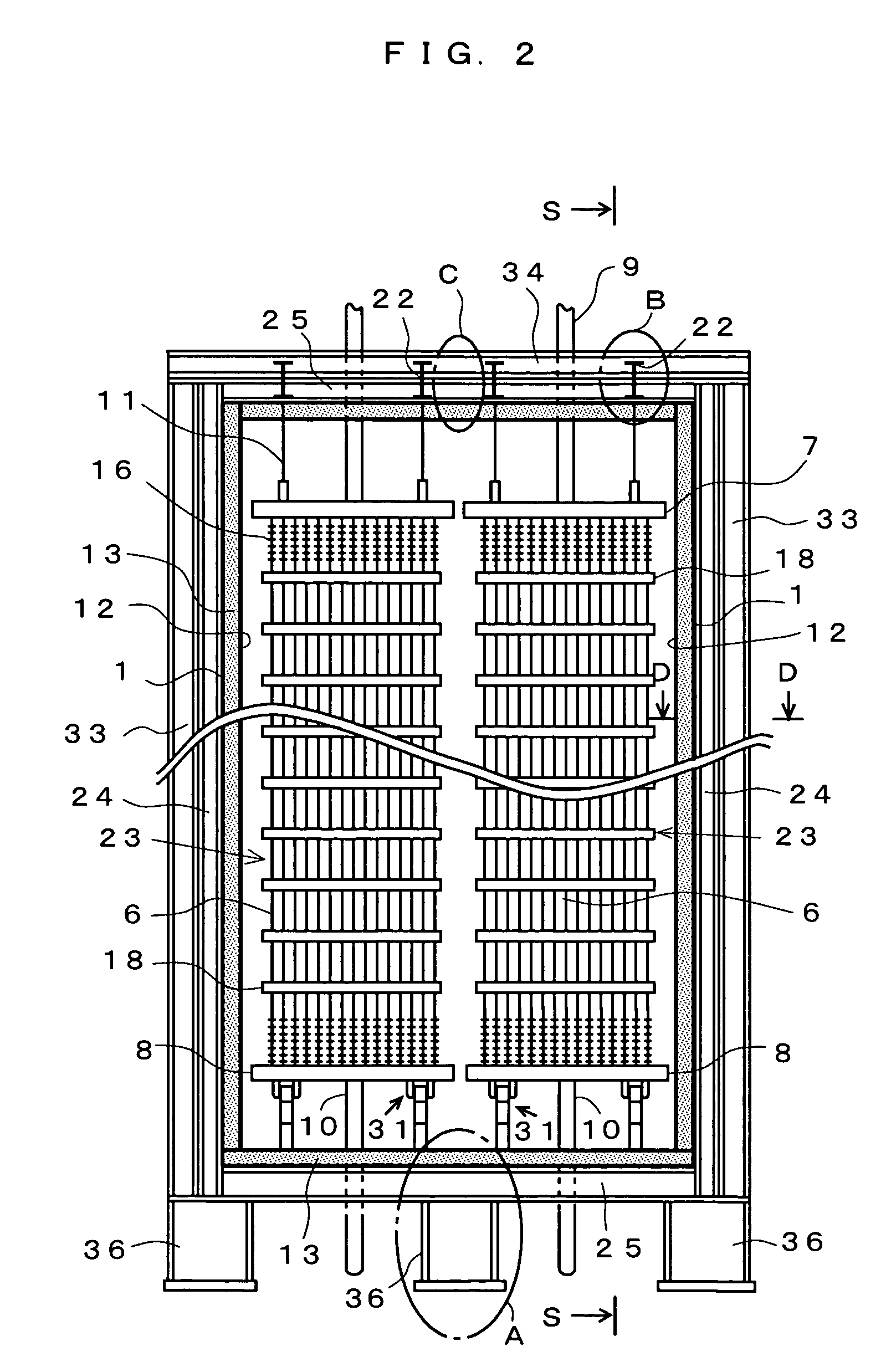
[0080]FIG. 4 is a side view of a heat exchanger tube bundle panel module 20 of the invention. One through several heat exchanger tube bundle panels 23 each including a plurality of fin-attached heat exchanger tubes 6, the upper header 7, and the lower header 8, etc., are arranged in parallel to the gas flow direction to form a module, and are integrated with vertical module frames 24 (24a, 24b) and horizontal module frames 25 that are commonly used as transporting frames are integrated together to obtain each heat exchanger tube bundle panel module (hereinafter, may be simply referred to as a module) 20. The number of panels in the heat exchanger tube panel module 20 is set by considering the limits in transportation to the construction site, installation efficiency at the installation site, and limitations due to system performance, etc.

[0081]Therefore, in one heat exchanger tube panel module 20, heat exchanger tube bundle panels 23 including many (for example, 600) heat exchanger ...

second embodiment

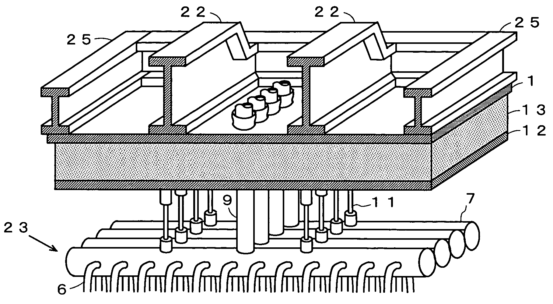
[0093]FIG. 7 shows a heat exchanger tube bundle panel module 20 of the invention. This module 20 is transported by laying the side wall face horizontally, so that the side view of the horizontally laid state is shown in FIG. 7. Inside the casing 1 (the casing 1 including a lamination of the liner 12 and the heat reversing material 13 inside may be simply referred to as a casing) including a lamination of the liner 12 and the thermal insulating material 13 inside, a plurality of heat exchanger tube bundle panels 23 each including a number of heat exchanger tubes 6, an upper header 7 and a lower header 8 thereof, and vibration restraining supports 18, etc., are housed.

[0094]Between the heat exchanger tube bundle panels 23 and the casing 1, transporting spacers 61 that fix the heat exchanger tube bundle panels 23 are set between the vibration restraining support 18 and the casing 1 and between the lower header 8 and the casing 1.

[0095]In addition, lugs 60a and 60b are attached to the i...

third embodiment

[0109]FIG. 12 is a side view of a heat exchanger tube bundle panel module 20 of the invention.

[0110]This module 20 is transported by laying the side wall face horizontally, so that a horizontally-laid side surface is shown in FIG. 12. Inside the casing 1 including a lamination of the liner 12 and the thermal insulating material 13 inside (the casing 1 formed by laminating the liner 12 and the thermal insulating material 13 may be simply referred to as a casing), heat exchanger tube bundle panels 23 each including a number of heat exchanger tubes 6, an upper header 7 and a lower header 8 thereof, and vibration restraining supports 18, etc., are contained.

[0111]Between the heat exchanger tube bundle panels 23 and the casing 1, transporting spacers 61 for fixing the heat exchanger tube panels 23 during transportation are installed between the vibration restraining support 18 and the casing 1 and between the lower header 8 and the casing 1.

[0112]On the inner surfaces of the ceiling side...


PUM

PropertyMeasurementUnit
thicknessaaaaaaaaaa
temperatureaaaaaaaaaa
sizeaaaaaaaaaa

Abstract

A method of constructing an exhaust heat recovery boiler. A required number of heat transfer tube group panel modules (20) are produced in an appropriate size according to design specifications of HRSG, where the heat transfer tube group panel modules (20) each have a large number of heat transfer tubes (6), heat transfer tube group panels (23) constituted of upper and lower collection tubes (7, 8) for the heat transfer tubes (6), a casing (1) for the heat transfer tube group panels (23), heat transfer tube group panel supporting beams (22) provided outside a ceiling wall portion of the casing (1), and a vertical and horizontal module frames (24, 25) provided outside the casing (1). Main frames for supporting the modules (20), including main pillars (33), main beams (34), and bottom wall portion pillars (36), are constructed in advance in a construction site of the heat recovery boiler (HRSG). Each module (20) is transported to the construction site and lowered by a crane (42) into between adjacent main pillars (33). Supporting beams (22) of each module (20) are placed at the height of installation of the main beam (34). Then the horizontal module frames (25), the main beams (34), and the bottom wall portion pillars (36) are connected and fixed, and the vertical module frames (24) and the main pillars (33) are connected and fixed.

Description

TECHNICAL FIELD[0001]The present invention relates to an exhaust heat recovery boiler (hereinafter, also referred to as a heat recovery boiler) to be used in a commercial or industrial combined cycle power generation plant, more specifically, a construction method for a heat recovery boiler by fabricating a module of a heat exchanger tube bundle panel, and a heat exchanger tube bundle panel module to be used for construction of the exhaust heat recovery boiler.BACKGROUND ART[0002]A combined cycle power generation plant comprising of a combination of a gas turbine and a heat recovery boiler has a power generation efficiency higher than that of other thermal power generation plants, it mainly uses natural gas as a fuel, and it has less production of sulfur oxide and ash dust, so that its exhaust gas purification load is small, for which it has attracted a lot of attention as a successful power generation system. In addition, a combined cycle power generation plant is excellent in load...

Claims


Application Information

Patent Timeline
Patent Type & Authority Patents(United States)
IPC IPC(8): F22B37/24G21C13/024F22B1/18F28D7/16F28F9/013
CPCF28F9/013F22B1/1815F22B37/244F28D7/1615F22B37/242Y02E20/16Y10T29/49387F28D21/0003
Inventor WASEDA, ISAOYOSHIMOTO, YUZURUKITAHASHI, YOSHIKISHIGENAKA, TOSHINORIMUSASHI, MITSUGINISHIOKA, TORUKIRIYAMA, TATSUOMURAKAMI, EIIJI
Owner MITSUBISHI HITACHIPOWER SYST LTD
Why Eureka
Try Eureka