
Multi-zone firewall detection system

Inactive Publication Date: 2007-10-02
WALL TERRY M
View PDF15 Cites 83 Cited by
  • Summary
  • Abstract
  • Description
  • Claims
  • Application Information

AI Technical Summary

Benefits of technology

[0012]In view of the foregoing background, it is therefore an object of the present invention to provide a multi-zone fire detection system. These and other objects, features, and advantages of the invention are provided by a camouflaged thermo-sensitive sprinkler system for protecting a building structure from wildfire damage.
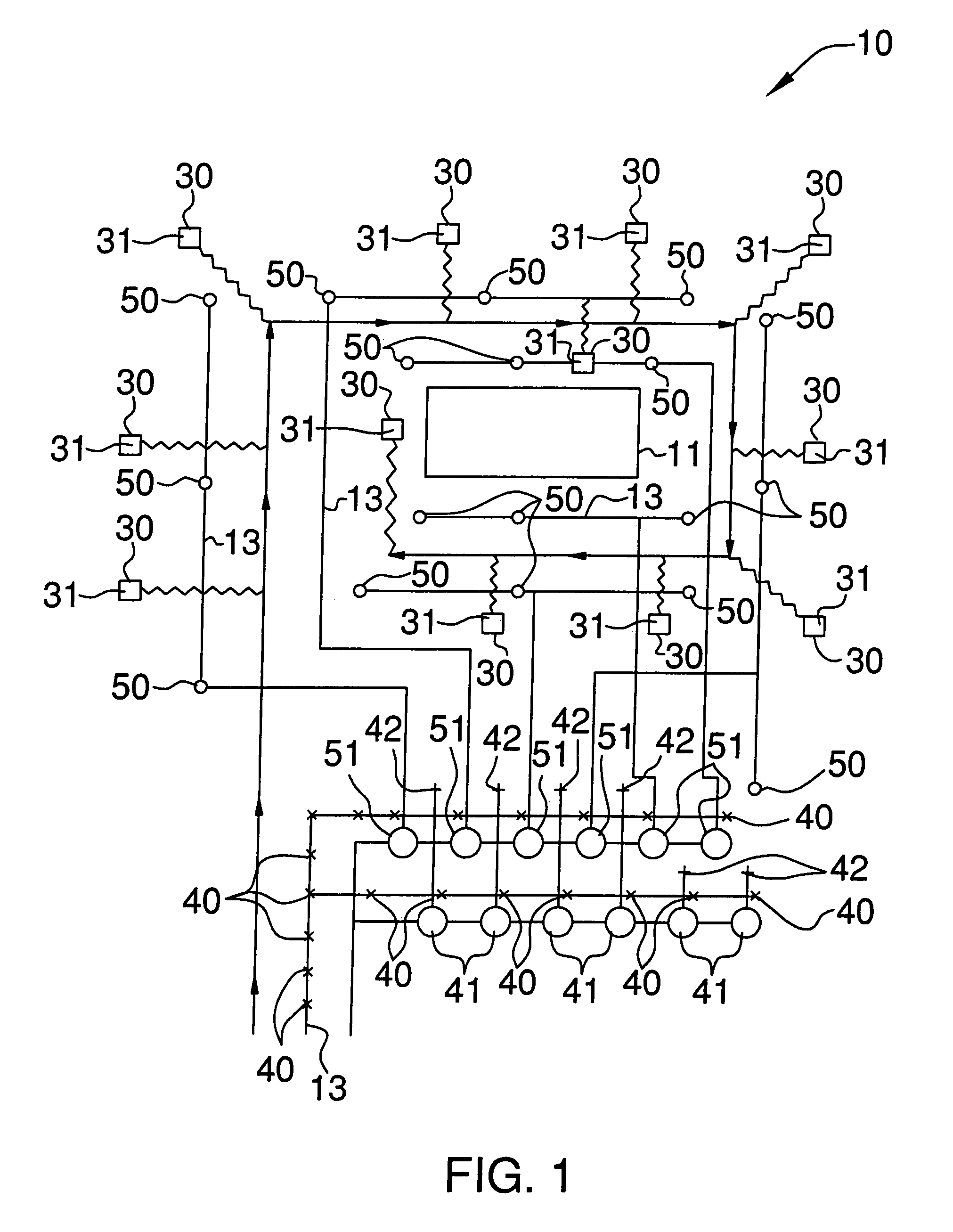
[0015]A plurality of lawn sprinkler assemblies are selectively positioned at predetermined locations about the perimeter of the building structure. Such lawn sprinkler assemblies preferably include a plurality of one-way shut-off valves located down stream of a main water supply line and a plurality of sprinkler heads in fluid communication with the shut-off valves respectively. The sprinkler heads are selectively positioned in a plurality of zones defined about the perimeter of the building structure. Each zone is directly operable by an associated one of the shut-off valves such that selected ones of the zones can advantageously and conveniently be activated as needed.
[0016]A plurality of fire sprinkler assemblies are selectively positioned at predetermined locations about the perimeter of the building structure. Such fire sprinkler assemblies preferably include a plurality of one-way shut-off valves located down stream of a main water supply line and a plurality of sprinkler heads in fluid communication with the shut-off valves respectively. The sprinkler heads are selectively positioned in a plurality of zones defined about the perimeter of the building structure. Each zone is directly operable by an associated one of the shut-off valves such that selected ones of the zones can advantageously and conveniently be activated as needed.
[0017]Such lawn sprinkler assemblies and fire sprinkler assemblies are electrically mated to the control panel and are further independently operable during emergency and non-emergency situations. Each sensor is in communication with the control panel such that the sensors can advantageously automatically instruct the control panel to activate and deactivate the lawn and fire sprinkler assemblies when an ambient temperate is detected to be higher than a maximum threshold temperature surrounding the building structure. The lawn shut-off valves are preferably connected in series and isolated from the fire shut-off valves such that the lawn and fire shut-off valves can effectively be independently operated and thereby advantageously allow corresponding ones of the zones to be independently operated.
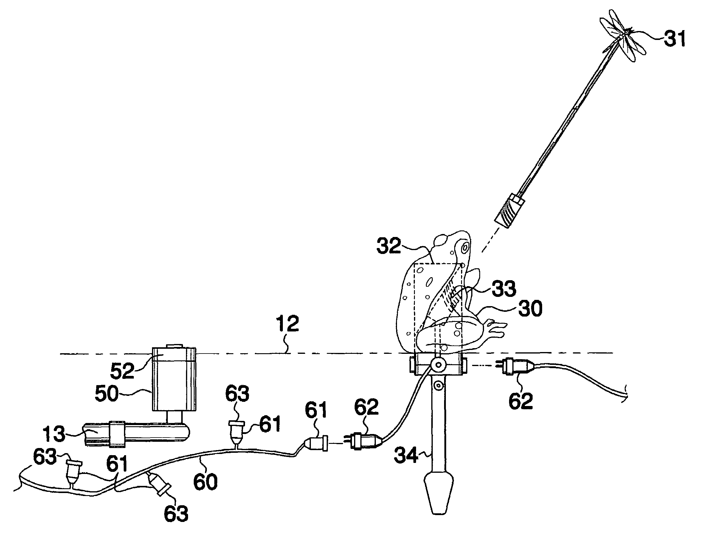
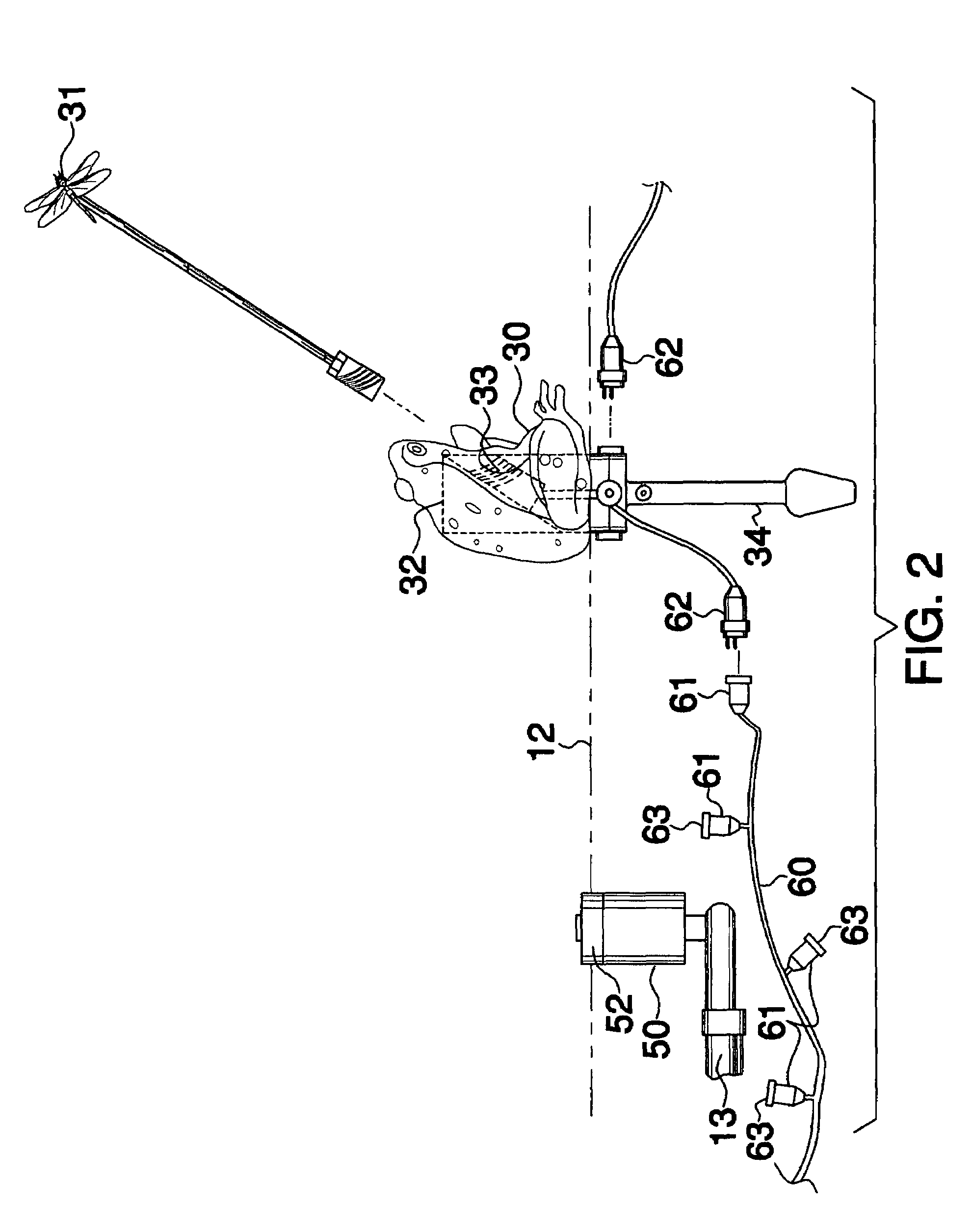
[0018]The system may further include at least one elongated and conductive cable including a plurality of female couplings electrically mated thereto and laterally extending away from the cable. Such a cable further includes a male coupling electrically mated thereto. A female receptacle is directly mateable to the male coupling of the cable such that spaced ones of the sensors can effectively be powered by associated ones of the cable. A male receptacle is electrically coupled to the threaded bore and removably mateable with one female coupling of the cable. Such female couplings may include a cap removably attached directly to a receiving face of the female couplings for advantageously and effectively shielding the female couplings from undesirable debris during non-operating conditions.

Problems solved by technology

It is a problem for rural homeowners to protect their property from the danger of wildfires.
Residences built in these areas tend to be placed in locations that contain significant quantities of combustible vegetation and the structures themselves have combustible exterior walls and many have untreated wood roofs.
Many of these houses are also built on sloping hillsides to obtain scenic views; however, slopes create natural wind flows that increase the spread of a wildfire.
These homes are also located a great distance away from fire protection equipment and typically have a limited water supply, such as a residential well with a minimal water flow in the range of one to three gallons per minute.
Given this collection of factors, a wildfire entering this area is very difficult to control.
Wildfire can reach an intensity that causes uncontrollable and rapid spread due to spotting, which occurs as wind-borne burning embers are carried far ahead of the main fire front and land in receptive fuels.
These embers can fall on the roofs of houses, on woodpiles or can start new fires in the vegetation surrounding a structure while firefighters are occupied elsewhere with the main fire.
All prior art residential firefighting systems are grossly inadequate to deal with wildfires in the wild-land / urban interface area.
One of the most significant failings of all of these prior art fire fighting systems is that they are reactive by nature and serve to attempt to extinguish a fire that has begun on the roof of a structure.
Due to the limited supply of water in the homes in a wild-land / urban interface, such a method of defense is impractical as it can deliver a very limited amount of water to the structure that is ablaze.
In addition, the intensity of a wildfire quickly overwhelms these limited fire extinguishing measures since they are activated once the structure is on fire and / or the wildfire has reached the structure.
Many of these prior art systems operate in a preemptive manner and do not provide any environmental dependent measures to prevent the initiation of the fire or to thwart its spread.
The small size of the system components, as well as the decorative nature thereof, makes it comparatively unobtrusive, thereby preventing it from detracting from the appearance of a structure.

Method used


Image

  • Multi-zone firewall detection system
  • Multi-zone firewall detection system
  • Multi-zone firewall detection system

Examples


Embodiment Construction

[0034]The present invention will now be described more fully hereinafter with reference to the accompanying drawings, in which preferred embodiments of the invention are shown. This invention may, however, be embodied in many different forms and should not be construed as limited to the embodiments set forth herein. Rather, these embodiments are provided so that this application will be thorough and complete, and will fully convey the true scope of the invention to those skilled in the art. Like numbers refer to like elements throughout the figures.

[0035]The system of this invention is referred to generally in FIGS. 1-12 by the reference numeral 10 and is intended to provide a thermo-sensitive multi-zone fire detection system. It should be understood that the system 10 may be used to detect fires in many different types of settings and should not be limited in use to only rural residences and buildings.

[0036]Referring initially to FIGS. 1, 3 and 12, the system 10 includes a control ...


PUM


Abstract

A sprinkler system includes a control panel including a processor, a power supply source, and a memory including software instructions for automatically toggling the system between operating and non-operating modes. The control panel includes controls mated to the processor that generate and transmit a user input control signal thereto. The processor executes a control algorithm for enabling the user to override the system. Sensors are spaced along a perimeter of the building structure, are camouflaged and shaped as an outdoor ornamental lawn art such as insects and amphibians, and generate and transmit an RF detection signal to the control panel, identifying an ambient temperature. Lawn and fire sprinkler assemblies are positioned about the building structure. The lawn and fire sprinkler assemblies are mated to the control panel and are independently operable. The sensors automatically instruct the control panel to activate and deactivate the lawn and fire sprinkler assemblies when a threshold exceeding ambient temperate is detected.

Description

CROSS REFERENCE TO RELATED APPLICATIONS[0001]Not Applicable.STATEMENT REGARDING FEDERALLY SPONSORED RESEARCH OR DEVELOPMENT[0002]Not Applicable.REFERENCE TO A MICROFICHE APPENDIX[0003]Not Applicable.BACKGROUND OF THE INVENTION[0004]1. Technical Field[0005]This invention relates to fire detection systems and, more particularly, to a camouflaged thermo-sensitive multi-zone fire detection system for protecting a building structure from wildfire damage.[0006]2. Prior Art[0007]It is a problem for rural homeowners to protect their property from the danger of wildfires. There is an increasing trend for people to build their homes in locations that are within what is called the wild-land / urban interface. This is a term that describes the border zone where structures, mainly residences, are built in wild-land areas that by nature are subject to fires. The wild-land / urban interface describes the geographical areas where formerly urban structures, mainly residences, are built in close proximit...

Claims


Application Information

Patent Timeline
IPC IPC(8): A62C37/10A01G25/02A01G25/16A62C35/00A62C37/11A62C37/36A62C37/44
CPCA62C3/0214A62C3/0271A62C3/0292A62C37/10A62C37/36A62C37/44A62C35/58Y10S239/15
Inventor WALL, TERRY M.
Owner WALL TERRY M
Learn More