Device for simultaneously cooling and removing liquid from a gas from a compressor

a technology of compressors and liquids, which is applied in the direction of heating types, separation processes, applications, etc., can solve the problems of large damage risk, inefficient heat transfer, and detrimental presence of condensate in compressed gas, and achieves simple and convenient heat transfer, further improving the effect of condensate separation

Active Publication Date: 2007-10-02
ATLAS COPCO AIRPOWER NV
View PDF10 Cites 5 Cited by
  • Summary
  • Abstract
  • Description
  • Claims
  • Application Information

AI Technical Summary

Benefits of technology

[0024]Whereby Vg is the effective gas velocity, ρg is the density of the gas and ρv is the density of the cool fluid mixed with the condensate. The condensate separation is further improved by making the gas flow through a demisting device which is integrated in the pressure vessel above the distribution device of the cool fluid.
[0025]The cool fluid can be freely selected. If, however, its composition is identical to the composition of the condensate, the device will be simpler and cheaper as it is not required then to separate the cool fluid from the condensate.
[0026]In order to dry the compressed air, it is preferably heated by means of a heat exchanger which is erected at the top in the pressure vessel. Especially in this embodiment, the device is very compact. The heat required to this end is preferably abstracted from the cool fluid, so that less external cooling is required to cool the cool fluid before it makes direct contact with the compressed gas. Especially in the embodiment, built-in in the pressure vessel, and with the cool fluid as a heat source, this heat exchanger is much cheaper as no extra pressure-resistant casing is required, and the design pressure of this heat exchanger can moreover be low as it is not determined by the gas pressure but only by the hydrodynamic pressure drop in the circuit of the cool fluid.

Problems solved by technology

In many cases, this results in the compressed gas being saturated with these vapours and a part of the vapours being condensed during the cooling of the compressed gas.
For many applications, the presence of condensate in the compressed gas is very detrimental and the risk of damage is large when the gas is saturated with vapour.
The disadvantage of this gas drier is that the heat transfer is not very efficient and that moreover ice can be formed, which results in a large thermal resistance being built up which makes sure that the energy is used even less efficiently.
Another disadvantage of the gas drier from EP 0,120,547 is that use is made of an all-air heat exchanger which is inherently characterised by a high pressure drop in relation to the recycled energy.
A disadvantage of gas coolers in general is that they have to resist the high pressure of the compressed gas, that they are relatively expensive and cause a relatively large pressure loss of the compressed gas.
Condensate separators are either a relatively major source of pressure loss of the compressed gas, or they are not very efficient.
The heat exchangers of gas driers have to resist the high pressure of the compressed gas, they are voluminous and relatively expensive.
These heat exchangers, as well as the condensate separators of gas driers are a relatively major source of pressure loss for the compressed gas.
Moreover, the assembled device of the gas cooler, condensate separator and gas drier requires several connecting pipes which further increase the cost price of the device, as well as the pressure loss of the compressed gas.

Method used


Image

  • Device for simultaneously cooling and removing liquid from a gas from a compressor
  • Device for simultaneously cooling and removing liquid from a gas from a compressor
  • Device for simultaneously cooling and removing liquid from a gas from a compressor

Examples


Embodiment Construction

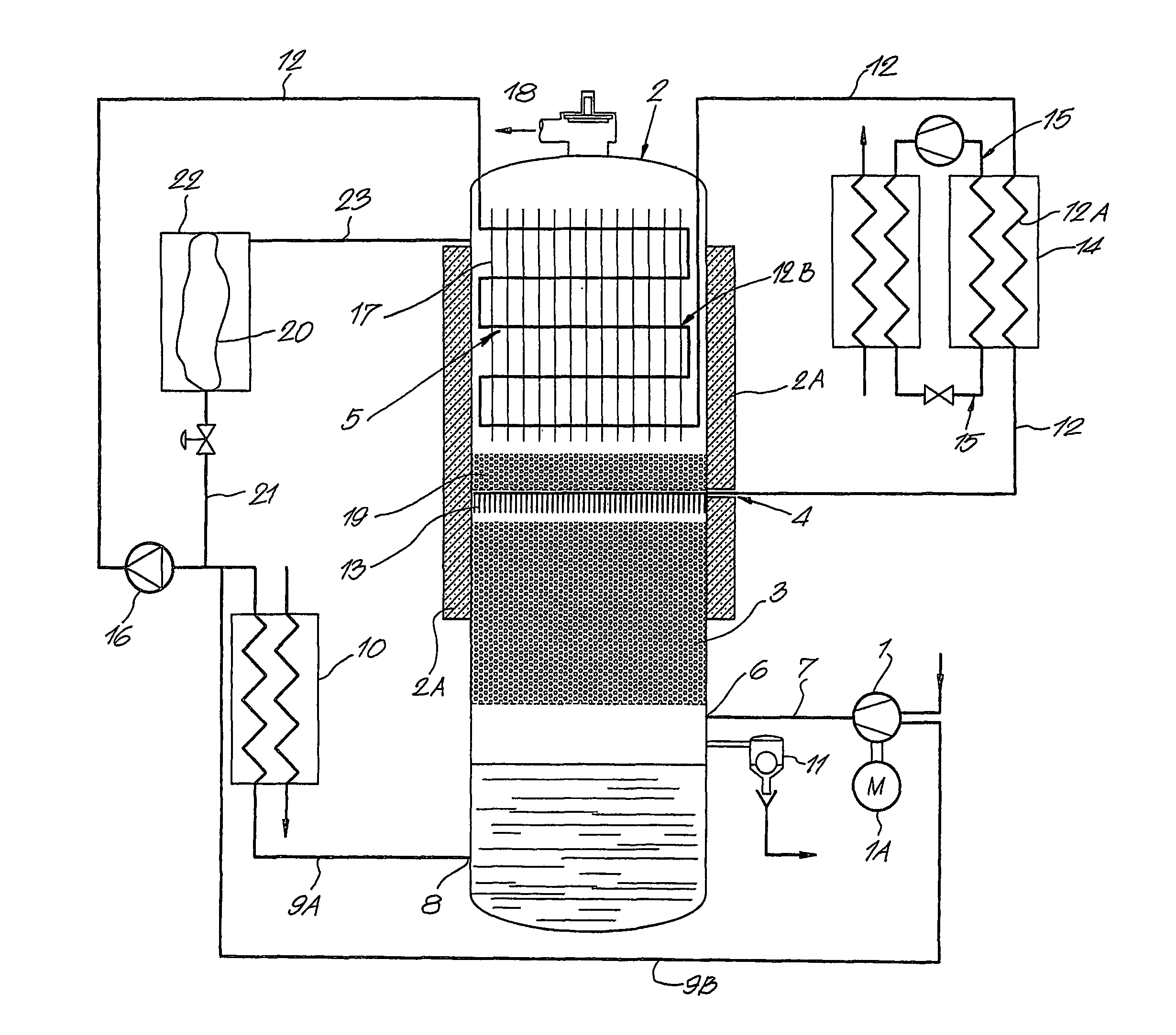
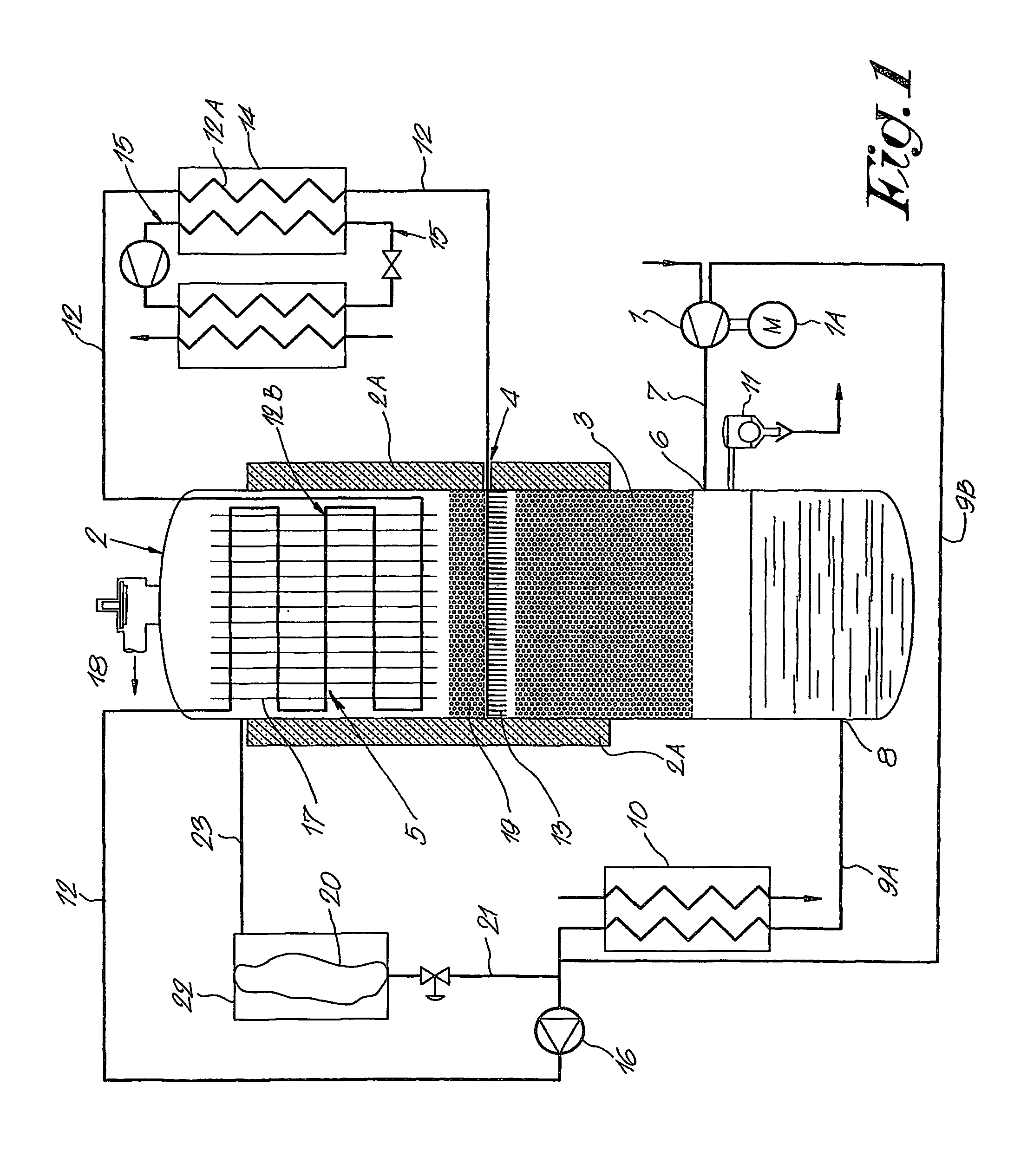
[0032]FIG. 1 represents a compressor with a screw compressor element 1, driven by a motor 1A, and a device for the cooling and liquid removal connected thereto, in particular water removal from the compressed gas, especially compressed air.

[0033]This device mainly comprises a pressure vessel 2 with insulation 2A with means in it to guarantee a direct contact between the compressed air and the cool medium, preferably water, which means consist of a contactor 3 and a water distribution device 4, and further, in the case of gas drying, also a heat exchanger 5 for re-heating the gas cooled in the contactor 3.

[0034]The pressure vessel 2 is a cylindrical, standing vessel with, at a distance above the bottom, an inlet 6 for compressed air which is connected to the outlet of the compressor element 1 by means of a compressed air line 7.

[0035]At the bottom, this pressure vessel is provided with a water drain 8 consisting of two parts 9A and 9B, with a heat exchanger 10 in between, which is co...


PUM

PropertyMeasurementUnit
temperatureaaaaaaaaaa

Abstract

Device for simultaneously cooling and removing liquid from compressed gas of a compressor element (1) or of several compressor elements (1) which are connected either or not in parallel or in series, which device includes a pressure vessel (2) which is provided with a liquid drain (8) at the bottom, an inlet (6) for compressed gas at a distance above the latter and an outlet (18) for compressed gas at the top, latter and an outlet (18) for compressed gas at the top, characterized in that a distribution device (4) is provided in the pressure vessel (2), between the inlet (6) and the outlet (18) for the compressed gas, for spreading a cool fluid in direct contact with the compressed gas, and in that a heat exchanger (5) is provided in the pressure vessel (2) for heating the compressed gas which has been cooled by the cool fluid.

Description

BACKGROUND OF THE INVENTION[0001]A. Field[0002]The present invention concerns a device for simultaneously cooling and removing liquid from compressed gas of a compressor element or of several compressor elements which are connected either or not in parallel and / or in series, which device comprises a pressure vessel erected in the compressed air line and which is provided with a liquid drain at the bottom, an inlet for compressed gas at a distance above the latter and a gas outlet at the top.[0003]B. Related Art[0004]In a liquid-injected compressor element is injected water, oil or another liquid in the inlet air or in the rotor chamber for lubrication, cooling and sealing. The liquid is discharged together with the compressed gas and subsequently separated in a pressure vessel and cooled in a heat exchanger, after which it is injected again in the compressor element.[0005]When a gas, comprising vapours such as water vapour, is compressed and subsequently cooled, it may contain less ...

Claims


Application Information

Patent Timeline
Patent Type & Authority Patents(United States)
IPC IPC(8): B01F3/04B01D5/00B01D53/26
CPCB01D53/265B01D5/0039B01D53/26
Inventor HEIRMAN, PETER JOZEF
Owner ATLAS COPCO AIRPOWER NV
Why Eureka
Try Eureka