Braking system for a battery powered industrial truck

a technology for industrial trucks and brake systems, which is applied in the direction of brake systems, brake components, transportation and packaging, etc., can solve the problems of large wear and difficulty in identifying faults when braking lines break,

Active Publication Date: 2007-10-02
JUNGHEINRICH AG +1
View PDF17 Cites 5 Cited by
  • Summary
  • Abstract
  • Description
  • Claims
  • Application Information

AI Technical Summary

Benefits of technology

[0009]In the inventive braking system, a braking signal is produced by means of the brake pedal in a known manner. The braking signal is transformed into a desired braking force which is inputted to the control device of the driving motor. There, a first conversion unit converts the braking signal into a desired torque for the driving motor. Using the help of the travel control, the driving motor produces a braking torque, i

Problems solved by technology

In contrast, the disadvantages of hydraulic brakes are avoided, namely the lar

Method used


Image

  • Braking system for a battery powered industrial truck
  • Braking system for a battery powered industrial truck

Examples


Embodiment Construction

[0018]While this invention may be embodied in many different forms, there are described in detail herein a specific preferred embodiment of the invention. This description is an exemplification of the principles of the invention and is not intended to limit the invention to the particular embodiment illustrated

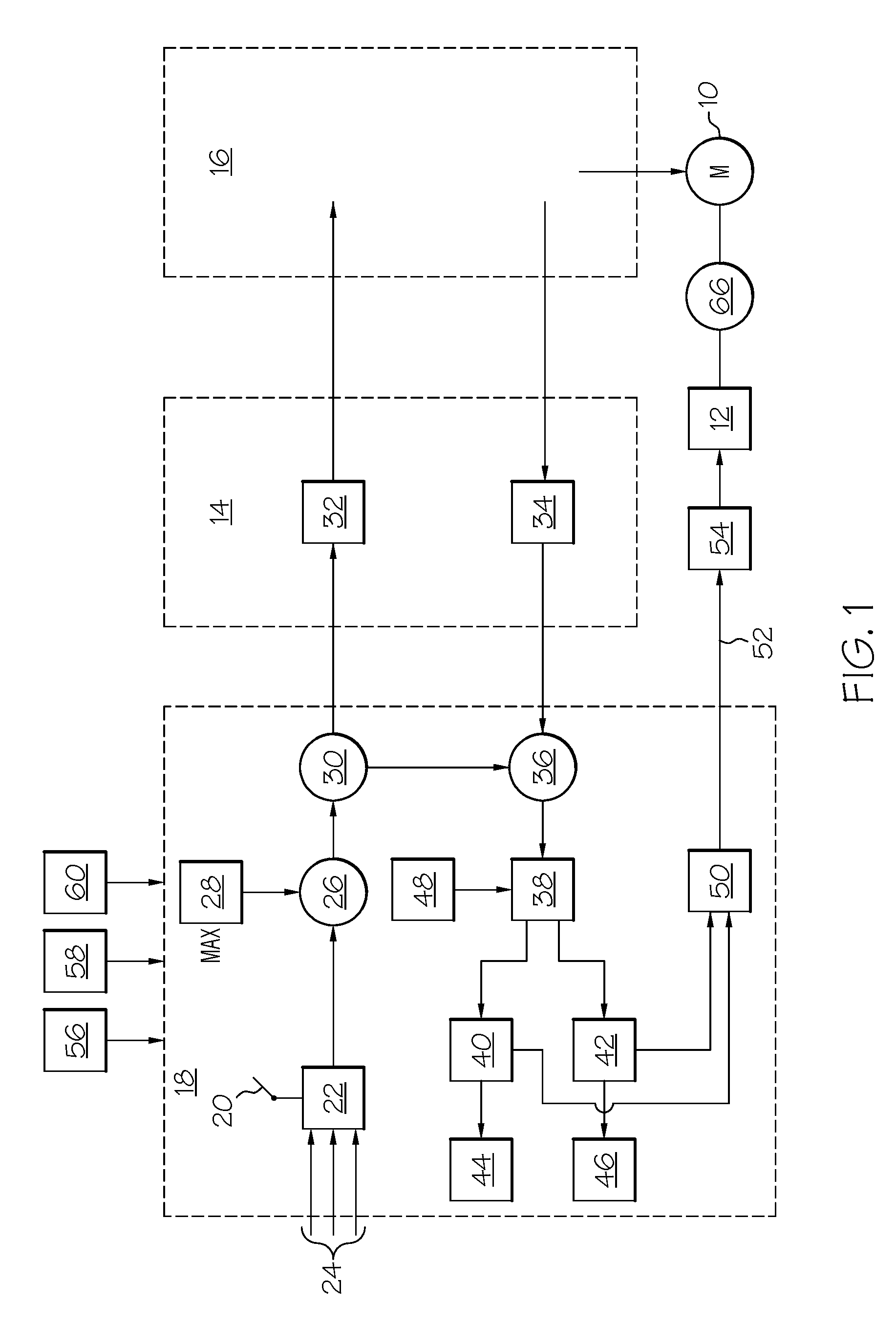
[0019]FIG. 1 shows a three-phase motor which drives a driving wheel, which is not shown, for an industrial truck. The driving wheel, which is not shown, has associated therewith a first braking device 12. The braking device 12 can also be associated with the shaft of the driving motor 10. A travel control, which is not explained in detail, for the battery-powered three-phase motor 10 is housed in the blocks 14, 16 shown in phantom lines. A braking control 18 is accommodated in the further block shown in phantom lines. A brake pedal 20 in the industrial truck, which is not shown, is actuated by the operator. A braking signal generator, which is actuated by the brake pedal 20, i...


PUM


Abstract

A braking system for battery-powered industrial trucks, comprising a three-phase driving motor which drives a driving wheel, a first braking device associated with the driving wheel, a brake pedal with which a braking signal generator is associated to generate an electric braking signal corresponding to a first desired braking force in response to the excursion of the brake pedal, a control device for the driving motor, a first conversion unit in the control device which converts said braking signal into a desired torque for the driving motor, a second conversion unit in the control device which converts the actual torque of the driving motor into an actual braking force, a comparator device in a braking control in which the first desired braking force is compared to the actual braking force to form a second desired braking force for the second braking device.

Description

CROSS-REFERENCE TO RELATED APPLICATIONS[0001]Not applicable.STATEMENT REGARDING FEDERALLY SPONSORED RESEARCH[0002]Not applicable.BACKGROUND OF THE INVENTION[0003]Industrial trucks of this type mostly have a driving wheel driven by an electric motor and idling load-carrying wheels. It is known to associate brakes with both the driving wheel and load-carrying wheels. The brake for the driving wheel can also be associated directly with the driving motor. It is known to employ hydraulic drum brakes for the brakes described. It is also known to use single-disc spring force loaded magnetic brakes for the driving motors. Those are mostly designed as so-called “fail-safe” brakes because there is a prescription that if an electric steering, as is frequently used for such industrial trucks, fails the vehicle requires to be slowed down in a regular manner.[0004]For industrial trucks provided with three-phase motors, it is also known to be slowed down by means of the driving motor that acts as ...

Claims


Application Information

Patent Timeline
IPC IPC(8): B60T13/74B60T8/60B60L7/18B60L7/24
CPCB60L7/18B60L7/24Y10S303/02B66F9/07509
Inventor HUTHER, SEBASTIANMANKEN, FRANKNISSEN, NIS-GEORG
Owner JUNGHEINRICH AG
Why Eureka
Try Eureka