Generator powered bicycle headlamp and electrical circuit

a technology of electric circuit and bicycle headlamp, which is applied in the direction of bicycle equipment, lighting and heating apparatus, optical signals, etc., can solve the problems of large friction resistance, dragging cyclists, and difficulty in pressing the roller against the side of the tire,

Inactive Publication Date: 2007-10-02
AKIELECTRIC KABUSHIKIGAISYA
View PDF30 Cites 57 Cited by
  • Summary
  • Abstract
  • Description
  • Claims
  • Application Information

AI Technical Summary

Benefits of technology

[0010]A further feature of the present invention is a bicycle headlamp, wherein a plurality of light-emitting diodes are used; the lens is a dome-shaped lens disposed for each of the light-emitting diodes, the dome-shaped lens having a curvature, a diameter, and a thickness calculated to obtain a specified level of illumination in a specified circle at a specified distance by focusing light; and a reflector is provided on a flat-plate portion above the lens, by applying a treatment for producing diffused reflection, so that the approach of the bicycle can be noticed ahead of the bicycle.

Problems solved by technology

This method exerts a large frictional resistance on the rotary motion, and the cyclist feels a drag while pedaling.
The conventional generator using the roller to be pressed against the side of the tire, however, must be turned on manually, and thus a trouble-free simple device has been needed.
The conventional method of pressing the roller against the side of the tire has problems.
A first problem is that the roller pressed against the side of the tire while cycling at night incurs a frictional resistance on the rotary motion, causing the cyclist to feel that the pedals have become heavy.
A second problem is that illumination will decrease when cycling on a muddy road because mud getting in between the tire and the roller causes the roller to slide along the tire.
A third problem is the need to manually turn on and turn off the generator for cycling at night.

Method used


Image

  • Generator powered bicycle headlamp and electrical circuit
  • Generator powered bicycle headlamp and electrical circuit
  • Generator powered bicycle headlamp and electrical circuit

Examples


first embodiment

[0040]FIGS. 1 to 17 are views showing a bicycle headlamp and a headlamp electrical circuit according to the present invention.

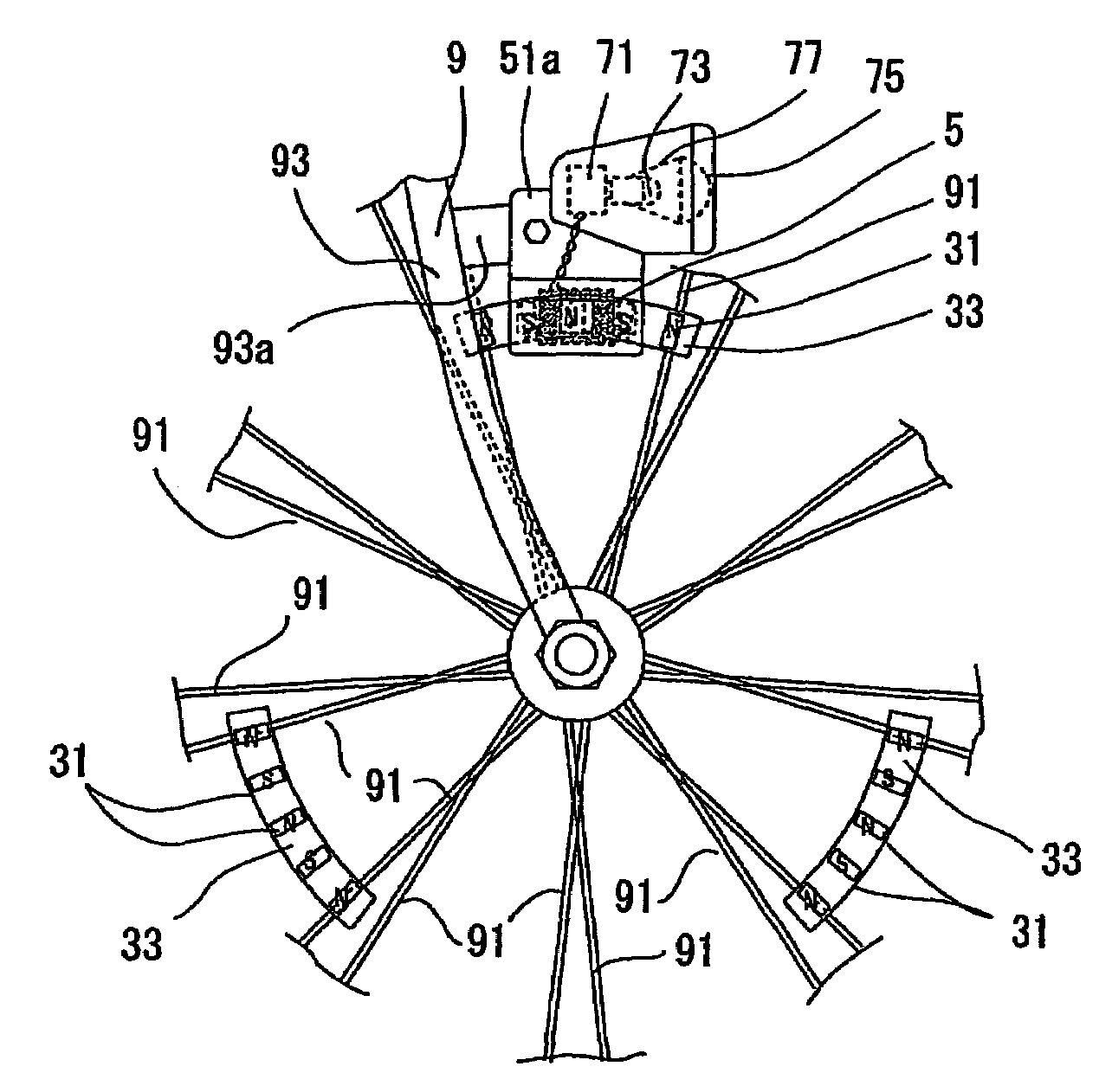
[0041]FIG. 1 is a view showing the bicycle headlamp according to the first embodiment of the present invention, namely, a side view showing a plurality of magnet plates attached to spokes of a bicycle wheel at particular spacings.

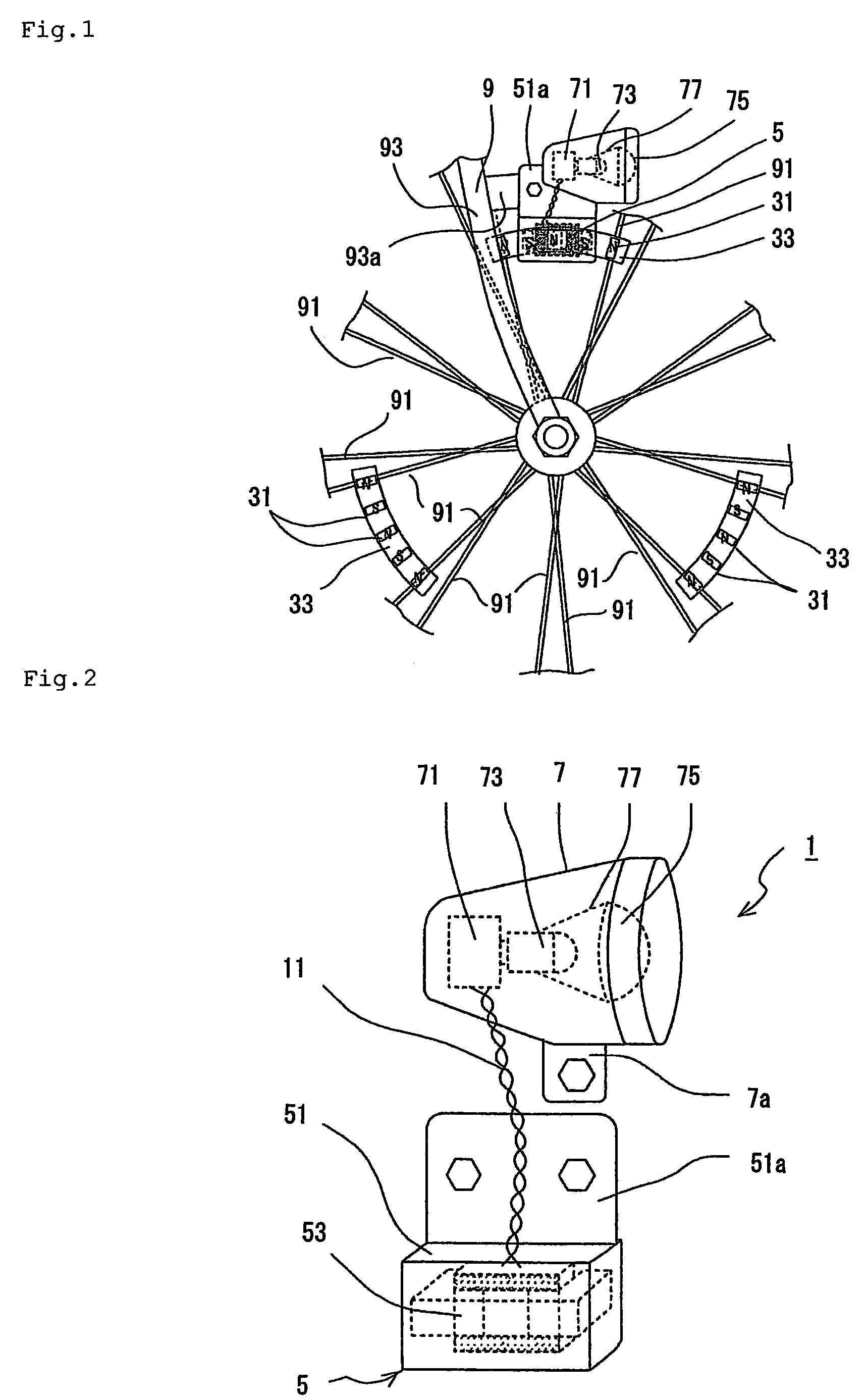
[0042]FIG. 2 is a perspective view showing the bicycle headlamp according to the first embodiment of the present invention, in which a stator, including a power-generating coil, is separated from a case.

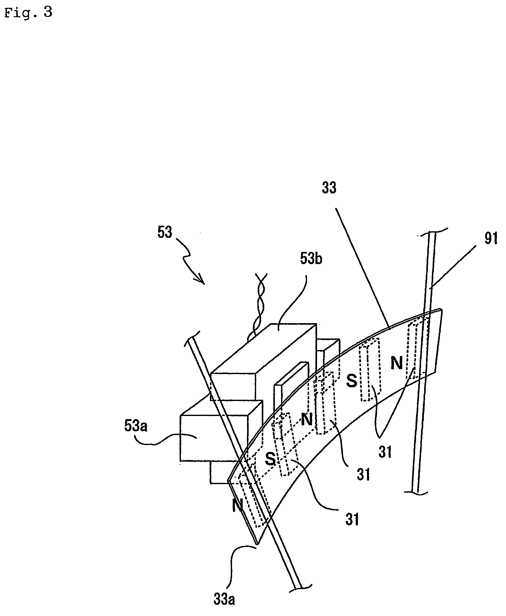
[0043]FIG. 3 is an enlarged perspective view showing a rotor and the stator of the bicycle headlamp according to the first embodiment of the present invention.

[0044]FIG. 4 shows enlarged views of a part of the rotor of the bicycle headlamp according to the first embodiment of the present invention: FIG. 4(a) is an enlarged front view of the magnet plate of the rotor; and FIG. 4(b) is an enlarged side view of the magnet plate of the ro...

second embodiment

[0078]It is easily understood that power is generated intermittently because the magnet plates 33 of the rotor 3 are disposed, as described above, at particular spacings on the wheel spokes 91 of the bicycle 9 in the bicycle headlamp and the headlamp electrical circuit using the resonant rectifier circuit. A headlamp electrical circuit according to the present invention appropriately smoothes out even the power generated intermittently, as described above, and can supply direct-current power containing a very small amount of ripple. The structure and the effects will be described below.

[0079]FIGS. 15 to 19 are views provided to describe the headlamp electrical circuit according to the second embodiment of the present invention.

[0080]FIG. 15 is a schematic diagram showing the headlamp electrical circuit according to the second embodiment of the present invention. FIG. 16 is a schematic diagram showing a resonance circuit and a dc-dc converter of a rectifying and smoothing circuit, in...

third embodiment

[0115]FIG. 21 is a schematic diagram showing the structure of a headlamp electrical circuit according to the present invention, including a light sensor or a manual switch for turning the light on or off.

[0116]FIG. 21 shows that a light sensor 13 and / or a manual switch 15 is added to the constant-current circuit 713b of the rectifying and smoothing circuit 713.

[0117]In the constant-current circuit 713b, the light sensor 13 is connected between the base (B) of the transistor TR2 and the emitter (E) of the transistor TR1 connected via the resistor R2, or between the collector (C) and the emitter (E) of the transistor TR1. The transistor TR2 turns on or off in accordance with a sense signal from the light sensor. This allows or interrupts current supply to the light-emitting diodes 73.

[0118]In the constant-current circuit 713b, the manual switch 15 may be connected between the base (B) of the transistor TR2 and the emitter (E) of the transistor TR1 connected via the resistor R2, or bet...


PUM


Abstract

A bicycle headlamp including: a rotor having a plurality of magnet plates attached to spokes of a bicycle wheel, each magnet plate including a plurality of magnets disposed at regular circumferential spacings with alternating south and north poles; and a stator including a power-generating coil disposed in a fixed position to face the magnetic pole faces of the magnet plates. A case includes at least a headlamp electrical circuit for establishing resonance with a certain relative speed of the magnets by means of the power-generating coil and a capacitor connected in series, and for rectifying, smoothing out, and outputting electric power obtained from the power-generating coil. Also included are a light-emitting diode and a condenser lens for focusing light emitted from the light emitting diode in front of the bicycle and for illuminating the roadway.

Description

TECHNICAL FIELD[0001]The present invention relates to bicycle headlamps which include at least a rotor provided with magnets attached to spokes of a wheel of a bicycle, a stator provided with a power-generating coil mounted to face the rotor, a headlamp electrical circuit, a light-emitting diode, and a condenser lens, the light-emitting diode being lit by electricity generated by pedaling, and also relates to headlamp electrical circuits.BACKGROUND ART[0002]Conventional bicycle headlamps using an incandescent lamp receive power for providing illumination sufficient for nighttime cycling from a rotary generator, to which a rotary motion is transferred by a roller pressed against a side of a tire. This method exerts a large frictional resistance on the rotary motion, and the cyclist feels a drag while pedaling. Accordingly, cycling at night requires extra power. The conventional generator using the roller to be pressed against the side of the tire, however, must be turned on manually,...

Claims


Application Information

Patent Timeline
Patent Type & Authority Patents(United States)
IPC IPC(8): B62J6/06B62J6/00B62J6/02B62J6/20F21W107/13H02K7/18
CPCB62J6/001B62J6/02H02K7/1869B62J6/20B62J6/06B62J6/01B62J6/028B60Q1/02
Inventor WATANABE, MASASHI
Owner AKIELECTRIC KABUSHIKIGAISYA
Why Eureka
Try Eureka